
Separating device for a battery module, battery module, and motor vehicle

A separation device and battery module technology, applied in the direction of battery/battery traction, electric vehicles, batteries, etc., can solve the problems of fluid channel damage, heat dissipation can no longer be guaranteed, and achieve the effect of good force

Active Publication Date: 2021-05-28
AUDI AG
View PDF14 Cites 0 Cited by
  • Summary
  • Abstract
  • Description
  • Claims
  • Application Information

AI Technical Summary

Problems solved by technology

[0007] A disadvantage of the integrated construction of the cooling or flow channels in the separator plate is that, when the battery cells expand, the fluid channels can be damaged and thus no longer able to Ensure adequate heat dissipation

Method used


Image

  • Separating device for a battery module, battery module, and motor vehicle
  • Separating device for a battery module, battery module, and motor vehicle
  • Separating device for a battery module, battery module, and motor vehicle

Examples


Embodiment Construction

[0039] The examples set forth below are preferred embodiments of the invention. In the example, the described components of the embodiments correspond to individual features of the invention which can be considered independently of one another, which in each case likewise improve the invention independently of one another. Accordingly, the present disclosure shall also include combinations of embodiments other than those shown. Furthermore, the described embodiments may also be supplemented by other features of the invention that have already been described.

[0040] In the figures, like reference numerals correspond to elements with the same function.

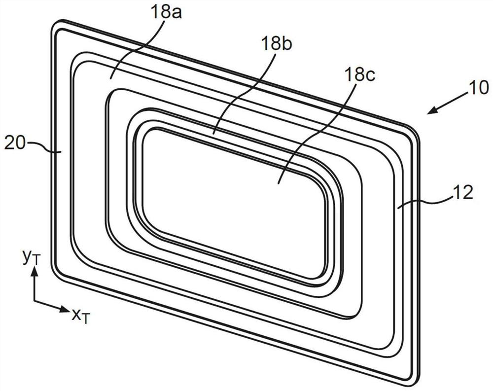
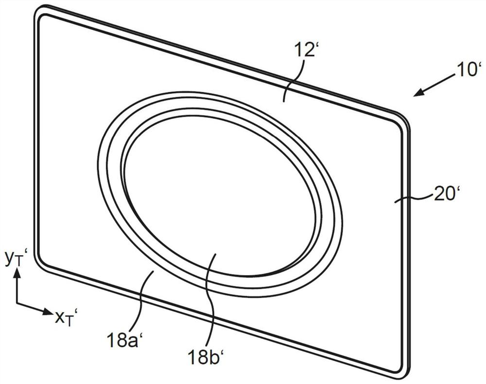
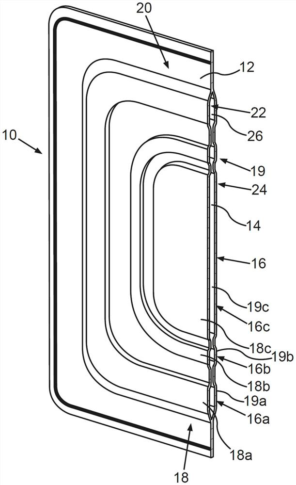
[0041] figure 1 is shown in a perspective view for the battery module (in figure 1 Separator 10 not shown). figure 2 An alternative design of the separating device 10' is shown. image 3 shown in cutaway figure 1 Separator 10. In the following, combined with Figure 1 to Figure 3 The construction and design of the div...


PUM


Abstract

A separating device 10 for a battery module 27. The separating device 10 includes a first separating element 12 and a second separating element 14, which are arranged congruently with respect to one another and adjacent one another. The first separating element 12 and the second separating element 14 are formed from a heat-conducting material. Furthermore, the two separating elements 12, 14 enclose a chamber 16 and the first separating element 12 and the second separating element 14 have embossments 18; 19 corresponding to one another for forming the chamber 16, wherein the embossments 18 of the first separating element 12 extend away from the second separating element 14 and the embossments 19 of the second separating element 14 extend away from the first separating element 12. The embossments (18; 19) are arranged opposite one another, and the chamber (16) is divided into a plurality of chamber region (16a, 16b, 16c) formed by the embossments (18; 19) of the first separating element (12) and the second separating element (14).

Description

technical field [0001] The present invention relates to a separator for battery modules. The separating device comprises a first separating element and a second separating element, which are arranged next to one another in a coinciding / overlapping manner. The first spacer element and the second spacer element are formed from a thermally conductive material. The invention also relates to a battery module comprising the separator according to the invention and to a motor vehicle with the battery module according to the invention. Background technique [0002] A battery module with battery cells, in particular lithium-ion cells, heats up during the charging and discharging phases. If the temperature reaches a critical value, auto-ignition occurs, which can also be referred to as thermal runaway propagation / expansion. In addition, the battery cells also expand during the charging and discharging phases, which may also be referred to as bulging. In order to prevent thermal ru...

Claims


Application Information

Patent Timeline
Patent Type & Authority Applications(China)
IPC IPC(8): H01M50/204H01M50/249H01M50/256H01M50/289B60L50/64
CPCB60L50/64H01M2220/20H01M10/61H01M10/625H01M10/647H01M10/655H01M10/6555H01M50/209H01M50/249H01M50/293H01M50/383Y02T10/70Y02E60/10H01M10/613H01M10/653H01M50/20H01M50/394
Inventor D·赫夫纳
Owner AUDI AG
Learn More