Micro base station redundancy deployment method, system, maintenance method and fault emergency method

A system maintenance and micro base station technology, applied in the redundant deployment of micro base stations, fault emergency field, can solve the problems of capacity limitation, remote coverage of faulty cells, deployment inapplicability, etc., to reduce costs, reduce maintenance costs and customer service pressure, The effect of improving real-time responsiveness

Pending Publication Date: 2021-05-28
江苏亨鑫众联通信技术有限公司
View PDF2 Cites 0 Cited by
  • Summary
  • Abstract
  • Description
  • Claims
  • Application Information

AI Technical Summary

Problems solved by technology

If it is used for the problem of the reduction of normal working stations caused by the failure of the base station, there is not enough time to complete the handover process. At the same time, when users collectively handover to adjacent cells, the throughput capacity will be limited
In addition, because the small base station of the adjacent cell is used to extend the coverage of the faulty cell, the signal quality will inevitably drop significantly
[0004] However, the existing BBU and RRU chain one-to-one redundant site deployment method will double the deployment cost for high-density and large-scale deployment of micro base stations. Except for some very special demand scenarios, for conventional Deployment does not apply
[0005] In addition, the existing method of preparing network planning plans for adjacent stations in advance uses adjacent base stations to cover the cell area responsible for the faulty base station. Since there are still multiple cells including the faulty cell covered by adjacent base stations, the capacity will be limited, so the improvement of user experience cannot fully meet the requirements of users and operators

Method used


Image

  • Micro base station redundancy deployment method, system, maintenance method and fault emergency method
  • Micro base station redundancy deployment method, system, maintenance method and fault emergency method

Examples


Embodiment Construction

[0023] The present invention will be described in detail below in conjunction with the accompanying drawings and specific embodiments. Note that the aspects described below in conjunction with the drawings and specific embodiments are only exemplary, and should not be construed as limiting the protection scope of the present invention.

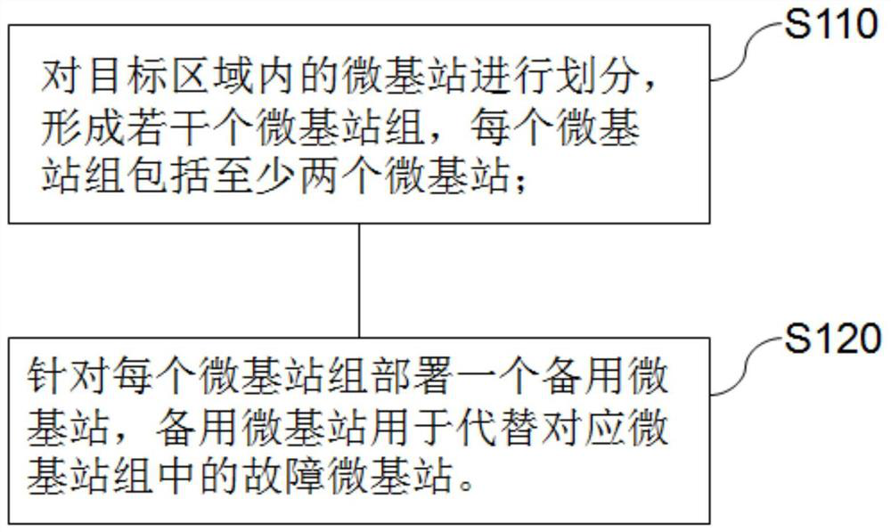
[0024] Such as figure 1 As shown, an embodiment of the present invention provides a redundant deployment method for a micro base station, including the following steps:

[0025] S110. Divide the micro base stations in the target area to form several micro base station groups, and each micro base station group includes at least two micro base stations;

[0026] S120. Deploy a standby micro base station for each micro base station group, where the standby micro base station is used to replace a faulty micro base station in the corresponding micro base station group.

[0027] The method adopts a one-to-many backup method, utilizes the adjustabi...


PUM


Abstract

The invention provides a micro base station redundancy deployment method, a system, a maintenance method and a fault emergency method. The deployment method comprises the following steps that micro base stations in a target area are divided to form a plurality of micro base station groups, and each micro base station group comprises at least two micro base stations; and a standby micro base station for each micro base station group is deployed, wherein the standby micro base station is used for replacing the fault micro base station in the corresponding micro base station group. According to the embodiment of the invention, by setting the one-to-many backup proportion of the backup micro base stations relative to the micro base station groups, compared with the one-to-one backup proportion, the cost is reduced, and the applicable scenes are greatly increased. In addition, the fault emergency real-time response capability of the micro base stations can be improved, and seamless switching between the backup base stations and the fault base stations is realized. Meanwhile, the backup base stations do not occupy the system resources and throughput capacity of the adjacent cells, so that equal system resources and equivalent signal quality can be provided for faulty cells.

Description

technical field [0001] The present invention relates to 5G base station deployment technology, in particular to a redundant deployment method, system, maintenance method and failure emergency method of a micro base station. Background technique [0002] The 5G system greatly improves user experience in terms of coverage and capacity through large-scale, high-density and highly flexible deployment of micro base stations. But conversely, when a single micro base station fails, leading to interruption of wireless signals, the damage to user experience may be greater than that of the previous generation system. That is, assuming that during normal operation, the communication rate of the 5G system is 10 times or higher than that of the previous generation system, then users will experience a performance improvement of 10 times or more from the positive experience. However, when the base station equipment fails and the signal is interrupted, assuming that the failure rate of the...

Claims


Application Information

Patent Timeline
IPC IPC(8): H04W16/18H04W24/04H04W88/08H04L12/24
CPCH04W16/18H04W24/04H04W88/08H04L41/0663
Inventor 王鹏徐国强华彦平
Owner 江苏亨鑫众联通信技术有限公司
Why Eureka
Try Eureka