Eureka AIR delivers breakthrough ideas for toughest innovation challenges, trusted by R&D personnel around the world.

Semi-submersible floating foundation for offshore wind power generation and cage culture

A cage culture and floating technology, applied in wind power generation, floating buildings, ships, etc., can solve the problems of structural fatigue, increase construction and post-maintenance costs, reduce steel consumption, strengthen stiffness and strength, reduce The effect of cost of use

Pending Publication Date: 2021-06-01
CSIC CHONGQING HAIZHUANG WINDPOWER EQUIP
View PDF0 Cites 4 Cited by
  • Summary
  • Abstract
  • Description
  • Claims
  • Application Information

AI Technical Summary

Problems solved by technology

[0004] At present, the main form of the semi-submersible is a column-stable structure, and the main bodies are connected by cross-bracing trusses. Usually, the cross-bracing trusses are composed of many struts, which not only increases the complexity of the entire floating foundation structure, but also Increased construction and post-maintenance costs, many strut structures make the structure fatigue problem prominent, at the same time, in order to ensure the stability of the entire floating wind power structure, the floating foundation needs to reach a certain draft, and the all-steel floating foundation requires greater external ballast

Method used


Image

  • Semi-submersible floating foundation for offshore wind power generation and cage culture
  • Semi-submersible floating foundation for offshore wind power generation and cage culture
  • Semi-submersible floating foundation for offshore wind power generation and cage culture

Examples


Embodiment Construction

[0028] In order to make the above objects, features and advantages of the present invention more comprehensible, specific implementations of the present invention will be described in detail below in conjunction with the accompanying drawings. In the following description, numerous specific details are set forth in order to provide a thorough understanding of the present invention. However, the present invention can be implemented in many other ways different from those described here, and those skilled in the art can make similar improvements without departing from the connotation of the present invention, so the present invention is not limited by the specific implementations disclosed below.

[0029] It should be noted that when an element is referred to as being “fixed” to another element, it can be directly on the other element or there can also be an intervening element. When an element is referred to as being "connected to" another element, it can be directly connected ...


PUM


Abstract

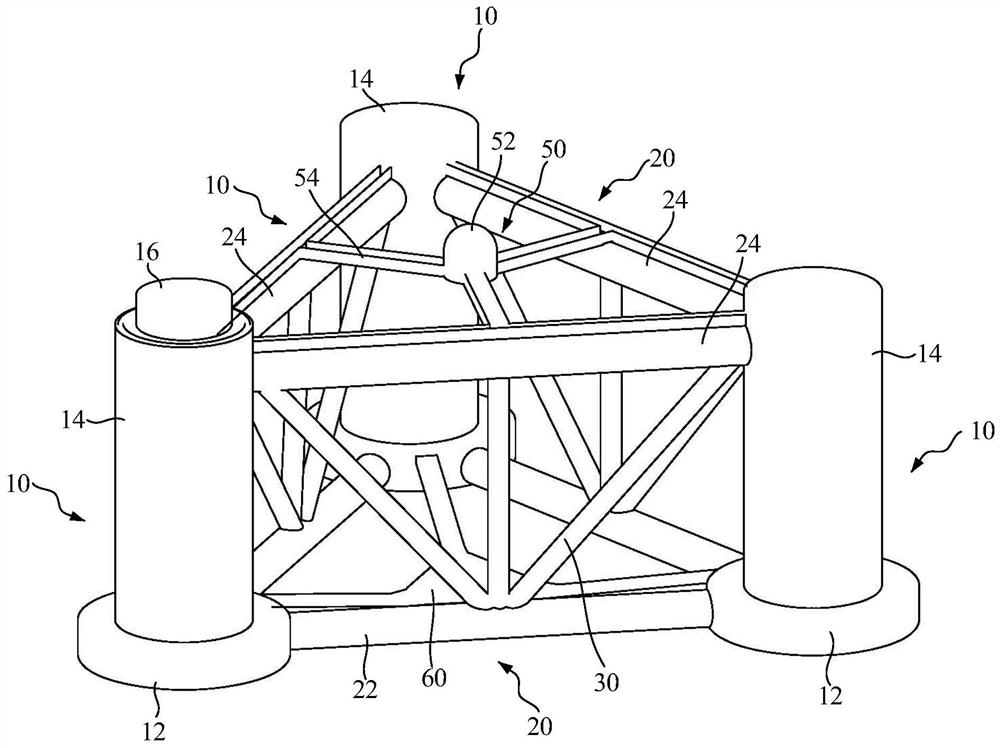
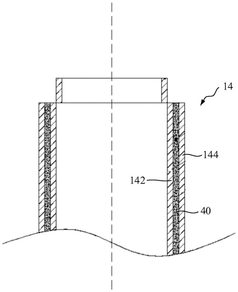
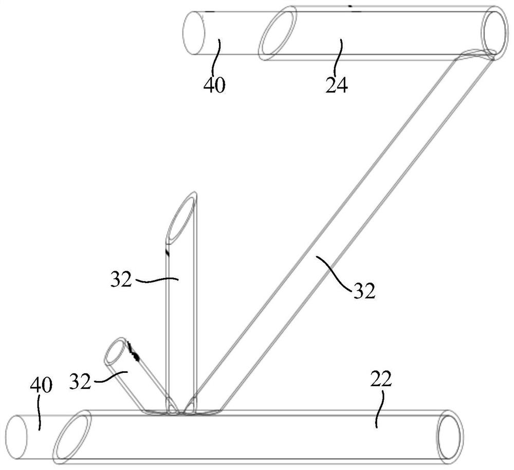
The invention discloses a semi-submersible type floating foundation for offshore wind power generation and cage culture. The semi-submersible type floating foundation comprises stand column units, transverse supporting assemblies, a truss structure and a culture cage, wherein the stand column unit comprises a heaving plate and a stand column, and the stand column is arranged on the heaving plate and filled with concrete; the transverse supporting assembly comprises a first transverse supporting rod and a second transverse supporting rod, the first transverse supporting rod is connected with the two adjacent heaving plates, the second transverse supporting rod is connected with the two adjacent stand columns, and the first transverse supporting rod and the second transverse supporting rod are both filled with concrete; and the truss structure is connected between the first transverse supporting rod and the second transverse supporting rod, a culture space is defined by the stand column units, the transverse supporting assemblies and the truss structure, and the culture cage is installed in the culture space. According to the semi-submersible floating foundation for offshore wind power generation and cage culture, the steel-concrete structure is used as fixed ballast, so that the draft of the floating foundation is increased, the steel consumption of the overall structure is reduced, meanwhile, the rigidity and strength of the local structure are enhanced, the material use cost is reduced, and the income is increased.

Description

technical field [0001] The invention relates to the technical field of wind power generation, in particular to a semi-submersible floating foundation for offshore wind power generation and cage culture. Background technique [0002] With the gradual saturation of wind resource exploitation in inland and offshore areas and the further increase in national energy demand, coupled with the high construction costs of offshore and deep-sea wind power and the development of composite industries, the offshore wind power industry has begun to try to integrate deep-sea aquaculture. and other industries to carry out research on composite industries, from the intertidal offshore area to the deep sea area. The shallow sea is closer to the coast, which is likely to have an impact on offshore fish farming and channel planning. Compared with shallow sea wind power, deep sea wind power has abundant wind resource reserves and stable wind resources. It has the advantages of high wind speed, lo...

Claims


Application Information

Patent Timeline
IPC IPC(8): B63B35/44
CPCB63B35/44B63B2035/442B63B2035/4453Y02E10/727
Inventor 周昊董晔弘周闯侯承宇周绪红王宇航陈帅倪远翔
Owner CSIC CHONGQING HAIZHUANG WINDPOWER EQUIP
Why Eureka
Eureka Blog
Learn More