A high-speed centrifugal compressor

A high-speed centrifugal and compressor technology, used in mechanical equipment, machines/engines, liquid fuel engines, etc., can solve problems such as reduced compression efficiency, single conduction path, and inability to cool down various functional components

Active Publication Date: 2021-09-14
YANTAI DONGDE IND CO LTD
View PDF0 Cites 4 Cited by
  • Summary
  • Abstract
  • Description
  • Claims
  • Application Information

AI Technical Summary

Problems solved by technology

[0009] In order to make up for the deficiencies of the prior art, the present invention provides a high-speed centrifugal compressor, which solves the problem that the previous internal air-cooling structure has a single conduction route, can only cool down individual components, and cannot cool down various functional components. The poor problem solves the problem of air leakage from the two-stage high-pressure chamber to the low-pressure chamber inside the centrifugal compressor and reduces the compression efficiency

Method used


Image

  • A high-speed centrifugal compressor
  • A high-speed centrifugal compressor
  • A high-speed centrifugal compressor

Examples


Embodiment Construction

[0041] In order to clearly illustrate the technical features of this solution, the present invention will be described in detail below through specific implementation modes and in conjunction with the accompanying drawings.

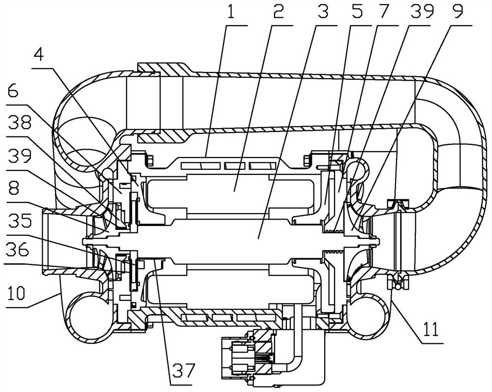
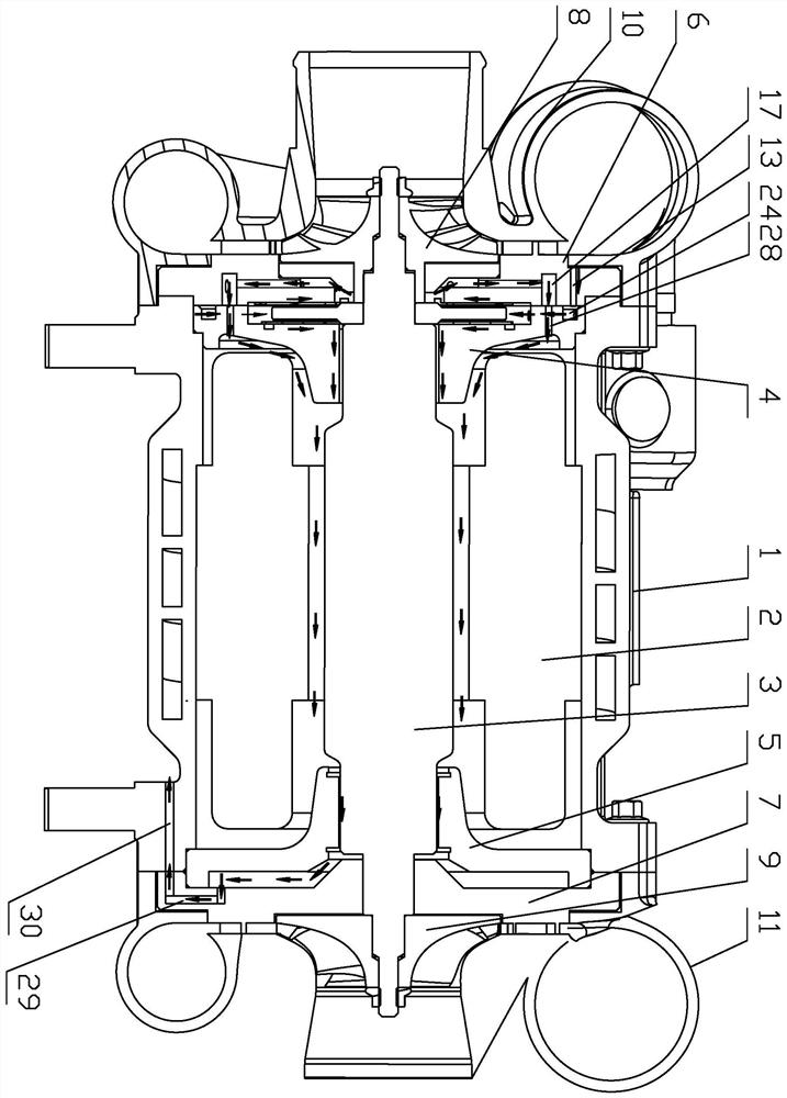
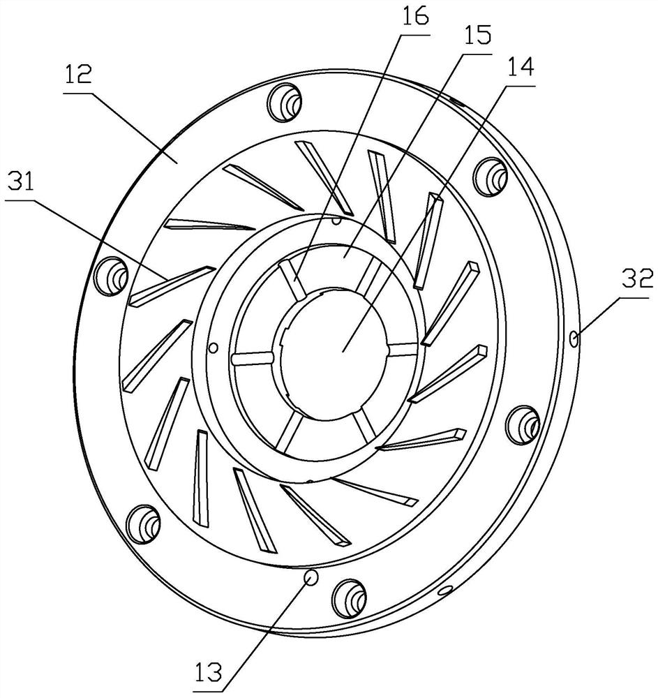
[0042] Such as Figure 1-12 As shown, a high-speed centrifugal compressor includes a housing 1, a stator 2, and a main shaft 3. The inner sides of both ends of the housing 1 are respectively installed with a primary bearing seat 4 and a secondary bearing housing 5 for supporting the main shaft 3. The housing 1 The first-stage diffuser 6 and the second-stage diffuser 7 are respectively installed on the outer sides of the two ends, and the first-stage diffuser 6 and the second-stage diffuser 7 pass through the two ends of the main shaft 3 to respectively install the first-stage worm gear 8 and the second-stage worm gear 9, A primary volute 10 and a secondary volute 11 are installed outside the primary worm wheel 8 and the secondary worm wheel 9, the primary...


PUM


Abstract

A high-speed centrifugal compressor, including a shell, a stator, and a main shaft. The inner sides of both ends of the shell are respectively installed with a primary bearing seat and a secondary bearing seat for supporting the main shaft. The gap between the primary diffuser and the primary bearing seat is The main shaft in between is provided with a thrust plate, and a thrust air bearing is provided on both sides of the thrust plate, and radial air bearings are respectively provided between the first-stage bearing seat and the second-stage bearing seat and the main shaft. A sealing end cover is provided between the first-stage worm wheel and the first-stage diffuser, several annular grooves are provided between the sealing end cover and the first-stage worm wheel, and several annular grooves are provided between the second-stage diffuser and the main shaft ; The housing is provided with a return air cooling system. Several air seals formed by the annular groove can greatly enhance the sealing effect between the high-pressure chamber and the low-pressure chamber, and improve the compression efficiency of the high-pressure chamber; the internal air-cooling structure is more optimized, the cooling effect is good, and the internal heat can be discharged in time without forming Heat build-up prevents forced shutdowns due to high internal temperatures.

Description

Technical field: [0001] The invention relates to a high-speed centrifugal compressor. Background technique: [0002] At present, the development of new energy fuel cell vehicles is considered to be an important link in the transformation of transportation energy and power. In order to ensure the normal operation of fuel cell engines, engines generally require auxiliary systems such as hydrogen supply subsystems, air supply subsystems, and circulating water cooling management subsystems. The research of [2] shows that the high-pressure, high-flow air supply has a significant effect on improving the power output of existing fuel cell engines. Therefore, before the general air enters the engine, it is necessary to pressurize the intake air. The centrifugal air compressor is an energy conversion device to achieve this goal, and it is one of the important components of the fuel cell engine air supply system. [0003] The structure of the current high-speed centrifugal compressor...

Claims


Application Information

Patent Timeline
Patent Type & Authority Patents(China)
IPC IPC(8): F04D17/12F04D29/44F04D29/58F04D29/057
CPCF04D17/122F04D29/441F04D29/582F04D29/057Y02E60/50F04D29/5806F04D29/444F04D29/056F04D29/0513
Inventor 王升科邢子义谢元豪
Owner YANTAI DONGDE IND CO LTD
Why Eureka
Try Eureka