[0024]In order to better understand the present invention, the technical solutions in the embodiments of the present invention will be described in connection with the drawings in the embodiments of the present invention, and the embodiments described herein will be clearly understood. It is an embodiment of the invention, not all of the embodiments. Based on the embodiments in the present invention, those of ordinary skill in the art will belong to the scope of the invention in the present invention without making in the pre-creative labor premise.
[0025]It should be noted that the specification and claims of the present invention and the terms "first", "second", "second" or the like are used to distinguish a similar object without having to describe a particular order or ahead order. It is to be understood that the data such as use can be interchanged in appropriate, so as to described herein. Moreover, the terms "including" and "having" and any variations are intended to cover non-rowing, such as process, methods, systems, products, or equipment that contain a series of steps or units, including a series of steps or units, are not necessarily limited to clearly listed. These steps or units may include other steps or units that are not clearly listed or for these processes, methods, products, or equipment.
[0026]In the present invention, the terms "top", "lower", "left", "right", "front", "top", "bottom", "inside", "in", "in", The orientation relationship between "vertical", "horizontal", "horizontal", "longitudinal", etc. is based on the orientation or positional relationship shown in the drawings. These terms are mainly to better describe the present invention and examples thereof, are not intended to define the indicated devices, elements or components must have a specific orientation, or constructive and operated in a specific orientation.
[0027]Further, the above-described term may be used to represent other meaning, such as the term "upper", in addition to the orientation, in addition to the orientation, may be used in some cases, may also be used to represent a certain dependency or connection relationship. These terms can be understood in terms of specific cases, depending on the specific circumstances.
[0028]In addition, the term "installation", "setting", "set", "connect", "connected", "set" should be a broad understanding. For example, it can be a fixed connection, a detachable connection, or an integral configuration; it can be a mechanical connection, or electrical connection; may be directly connected, or indirectly connected by an intermediate medium, or two devices, components or components. Interior of the interior. For those skilled in the art, the specific meanings of the above terms can be understood in terms of specific cases.
[0029]It should be noted that the features in the present invention in the present invention can be combined with each other in the case of an unable conflict. The present invention will be described in detail below with reference to the drawings.
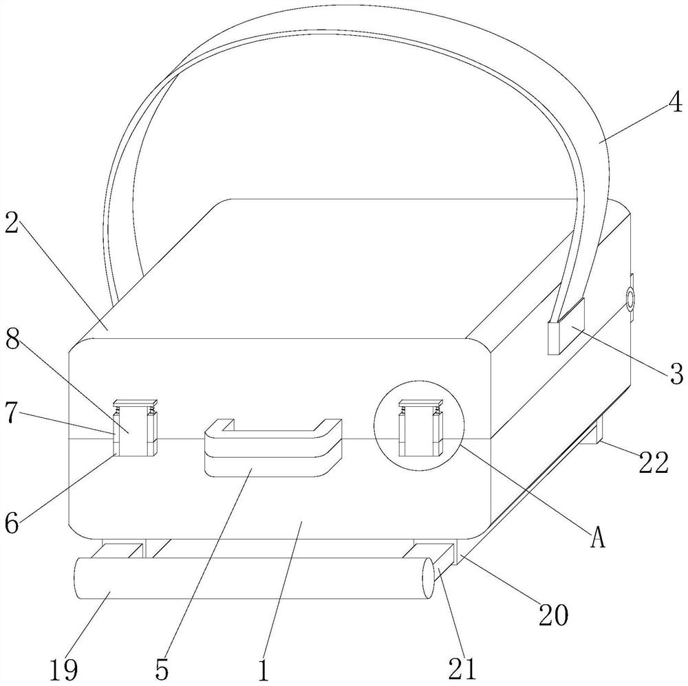
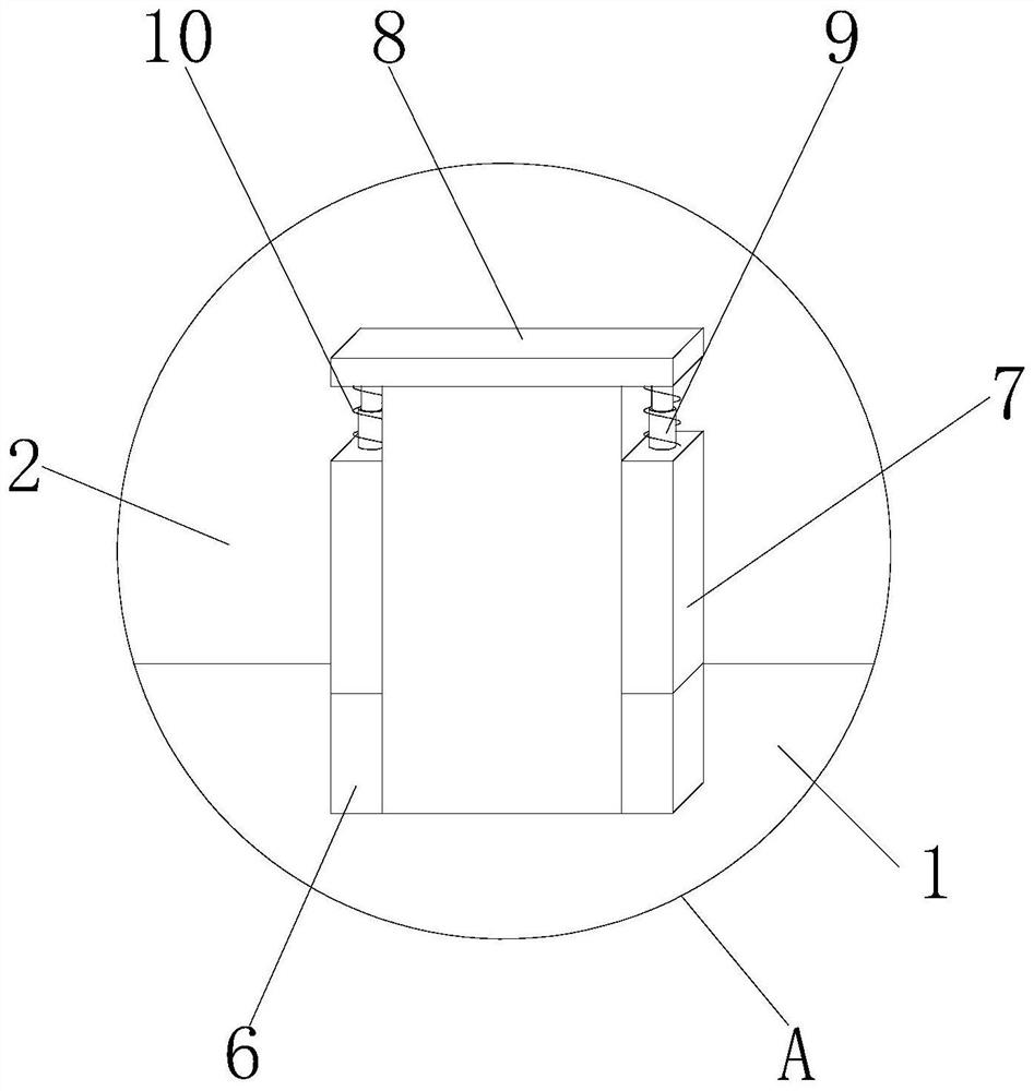
[0030]SeeFigure 1-5As shown, a mapping instrument for field engineering surveys, including fixing mechanisms, protective mechanisms, and mobile mechanisms including lower protective case 1, card slot 6, upper protective case 2, No. 1 telescopic rod 9 and No. 1 The spring 10 is rotatably coupled to the upper protective case 2, and the card slot 6 is fixedly coupled to the lower protective case 1, and the first chute 7 is fixed to the upper protective case 2, and No. 1 The chute 7 is slidable with the card plate 8, and the first end is fixed to the surface of the No. 1 chute 7, and the other end of the first telescoping rod is fixed to the surface of the card plate 8, the first spring 10 One end is fixed to the surface of the No. 1 chute 7, and the other end of the spring 10 is fixed to the surface of the card plate 8;
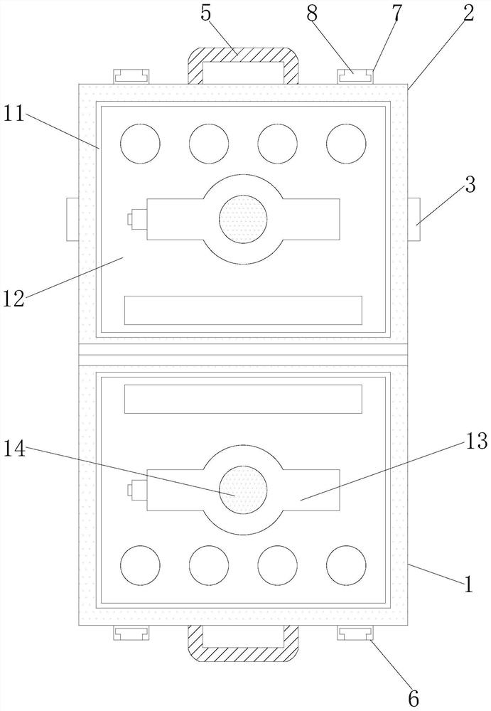
[0031]The protective mechanism includes a connecting case 11, a third telescopic rod 17, a three spring 18, a foam plate 12, a first, and a spring 16, and the connecting case 11 is slidably connected to the lower cover 1 inner surface. One end of the third telescopic rod 17 is fixed to the lower protective case 1, and the other end of the three telescopic rod 17 is fixed to the surface of the connecting case 11, and the three spring 18 is fixed to the lower protective case 1 surface, and The other end of the third spring 18 is fixed to the surface of the connecting case 11, the foam plate 12 is fixed to the surface of the connecting case 11, and the first connection plate 14 is slidably connected to the foam plate 12, and the first connection plate 14 surface and two When the telescopic rod 15 is fixed, the second telescopic rod 15 is fixed to the surface of the connecting case 11, and the second spring 16 is fixed to the surface of the No. 1 connection plate 14, and the second spring 16 is also The connection shell 11 is fixedly connected;
[0032]The moving mechanism includes a connection block 3, a second connection plate 22, a plug 23, a second slide 28, a fourth telescoping rod 26, and a springs 27, and the connection block 3 is fixedly connected to the upper cover 2 surface. Further, the connection block 3 is fixed to the strap 4, the second connection plate 22 is fixed to the surface of the lower protective case 1, and the second connection plate 22 is fixed to the surface of the connection outer tube 20, the connection outer tube 20 and the connection The tube 21 slides inserted, the connection inner tube 21 fixed to the tie rod 19, the plug 23, respectively, inserted with the connecting outer tube 20 and the connection inner tube 21, and fixed connection with the surface 24 of the tip 24 The other end of the fourth spring 24 is fixed to the surface of the connection outer tube 20, and the second slide groove 28 is fixed to the surface of the lower protective case 1, and the second slide 28 is slidable with the slider 29, the slip The block 29 is fixedly coupled to the three-connection plate 25, and the three-connection plate 25 is fixed to the wheel 30, and the fourth telescoping rod 26 is fixed to the surface of the three connecting plate 25, and the four telescopic rod 26. The connection is fixed to the surface of the second connection plate 22, and the second spring 27 is fixed to the surface of the three-connection plate 25, and the other end of the No. 5 spring 27 is fixed to the surface of the second connection plate 22.
[0033]The lower protective case 1 and the upper protective case 2 are provided with a handle 5, and two of the handle 5 are closely fitted, and the lower protective case 1 is provided with two card slots 6, two of the card slots 6. The symmetrical distribution is disposed on both sides of the handle 5, and the upper cover 2 is provided with two one slide grooves 7, two of the one slide 7 symmetry is distributed on both sides of the handle 5, and the one slide 7 and the card The plate 8 slides the connection, the cardboard 8 slides the cartridge 6, and the surface of the card plate 8 is provided with two first telescopic rods 9, and the two-first telescoped rod 9 is symmetric distributed in the surface of the card 8 surface. And the first telescopic rod 9 is disposed inside the first spring 10, and the lower protective case 1 and the upper protective case 2 are provided with a connecting case 11, and the two connecting cases 11 are respectively protected with the lower protective case 1 and the upper protection, respectively. The inner surface of the shell 2 is slidable, and several three telescopic rods 17 are provided inside the lower protective case 1 and the upper protective case 2, and the third telescopic rod 17 is uniformly distributed in the lower protective case 1 and the upper protective case 2 surface. And the third telescoping rod 17 is located inside the three spring 18, and the surface of the foam plate 12 is provided with an instrument placed slot 13, and a plurality of grooves are provided on the surface of the foam plate 12, and there are more surfaces. The second telescopic rod 15, the second telescoping rod 15 is uniformly distributed on the surface of the first connection plate 14, and the second telescoping rod 15 is located inside the second spring 16, and the connection inner tube 21 is provided with a plurality of jacks. The plug 23 is inserted through the surface of the connecting outer tube 20 with a jack, and the three connection plate 25 is provided with a plurality of wheels 30, the wheel 30 is uniformly distributed over the surface of the three-connection plate 25, the three The surface of the connection plate 25 is provided with a plurality of four telescopic rods 26, and the fourth telescoping rod 26 is uniformly distributed on the surface of the three connecting plate 25, and the fourth telescoping rod 26 is located inside the 5 spring 27.
[0034]When the application is in use, the measuring instrument is placed inside the instrument placement tank 13, and the other components are placed inside the groove of the surface of the foam plate 12, and the upper protective case 2 is rotated and the lower protective case 1 is closed, in the closed process. The cardboard 8 is pulled up, and the card plate 8 is contracted into a chute 7, and when the first chute 7 is bonded to the card slot 6, release the cardboard 8, through the No. 1 telescopic rod 9 and the first spring 10. The recovery-shaped beam pushes the cardboard 8 inserted into the card slot 6, so that the lower protective case 1 and the upper protective case 2 are fixed, and the instrument is wrapped by the foam plate 12, and the person carrying the instrument can select the strap 4 according to its own conditions and environment. The instrument is backed up, or the instrument is picked up, or the instrument can be pulled by the pull rod 19, and when pulling the insert 23, it is separated from the connecting inner tube 21, and the connecting inner tube is pulled through the tension 19. 21 Perform length adjustment, the length adjustment is appropriate, release the plug 23, and the connecting inner tube 21 is pulled by the first four spring 24, the length is fixed, and the length is fixed, and the instrument is pulled forward by the pulley 30, rolling When the person's physical consumption, the fourth telescopic rod 26 and the No. 5 spring 27 are subjected to a telescopic chasting, and the second telescopic rod 15 and the second spring 16, the third telescopic rod 17 and the third spring 18 telescopically Shock absorbing, protect the instrument to ensure that the instrument is not damaged during movement.
[0035]The beneficial place of the invention is:
[0036]1. In order to increase security, the measuring instrument is placed inside the instrument placement slot, and the other components are placed inside the groove of the surface of the foam plate, and the upper protective case is rotated and the lower protective case is closed, and the pull-up process is pulled upward. The cardboard, the cardboard is contracted into a slide, and the cardboard is released when the first slide is fitted with the card slot, and the first telescopic rod and the first spring recovery form into the card slot, Easy to connect, keep the lower protective case and upper protective shell securely;
[0037]2. In order to increase the protection of the instrument, the instrument is wrapped by the foam plate, and the fouling shock absorbers are carried out through the fourth telescopic rod and the five spring. At the same time, through the second telescopic rod and the second spring, third telescopic The rod and the third spring telescopic shock absorber, protect the instrument to ensure that the instrument is not damaged, and the shock absorption protection is carried out, and the instrument is damaged;
[0038]3. In order to facilitate carrying, the personnel carrying instruments can choose to bring the instrument by the strap according to its own conditions and environment, or picked the instrument by pulling the instrument by pulling the instrument, and pulling the instrument by pulling up The plug is disengaged from the inner tube, and the tube is pulled through the tube to pull the inner tube. After the length adjustment is properly released, the insert is released through the four spring, and the connecting insert is plugged, and the length is fixed, passed the lever The pulling instrument is advanced, and the physical power consumption of the personnel will be reduced by the wheel scroll.
[0039]It is merely preferred embodiments of the present invention, and is not intended to limit the invention, and the present invention can have various changes and variations for those skilled in the art. Any modification, equivalent replacement, improvement, etc. according to the spirit of the invention should be included within the scope of the invention.