Laser radar for space rendezvous and docking

A laser radar and space rendezvous technology, applied in the field of scanning and tracking control, can solve the problems of increased system volume, weight, and complexity, and achieve the effect of reducing weight and volume, improving accuracy, and achieving light and small size.

Pending Publication Date: 2021-06-01
INST OF OPTICS & ELECTRONICS - CHINESE ACAD OF SCI
View PDF6 Cites 7 Cited by
  • Summary
  • Abstract
  • Description
  • Claims
  • Application Information

AI Technical Summary

Benefits of technology

The present in this patented technology uses two different types of motors: one for pitch (pitch) motion and another type called an Azimuth or tilted direction sensor that tracks eye movements on both sides instead of just looking at them separately. This allows faster scans while maintaining precise alignment between targets and reduces its size compared to traditional methods like radar techniques. Additionally, it includes modules used to detect when there are other objects near where they shouldn't be seen during flight time. These features help reduce the overall weight and space needed per camera system. Overall, these technical improvements make capturing larger areas more efficient than current technologies such as radioactive ray tomography.

Problems solved by technology

Layered laser scattering (LSC) technique was proposed earlier but had limitations when applied to larger areas due to their lack of accuracy or responsiveness during long periods of time. To overcome these issues, there were proposes combining multiple measurements into one process called multi-dimensional coheroid survey (MCS). However, existing techniques have drawbacks like complex hardware systems requiring expensive components, slow response times, poor pointing capabilities, etc., making them difficult to implement at different locations within our country.

Method used


Image

  • Laser radar for space rendezvous and docking
  • Laser radar for space rendezvous and docking
  • Laser radar for space rendezvous and docking

Examples


Embodiment Construction

[0041] The following will clearly and completely describe the technical solutions in the embodiments of the present invention with reference to the accompanying drawings in the embodiments of the present invention. Obviously, the described embodiments are only some, not all, embodiments of the present invention. Based on the embodiments of the present invention, all other embodiments obtained by persons of ordinary skill in the art without making creative efforts belong to the protection scope of the present invention.

[0042] The object of the present invention is to provide a laser radar for space rendezvous and docking, so as to reduce the volume and weight of the laser radar.

[0043] In order to make the above objects, features and advantages of the present invention more comprehensible, the present invention will be further described in detail below in conjunction with the accompanying drawings and specific embodiments.

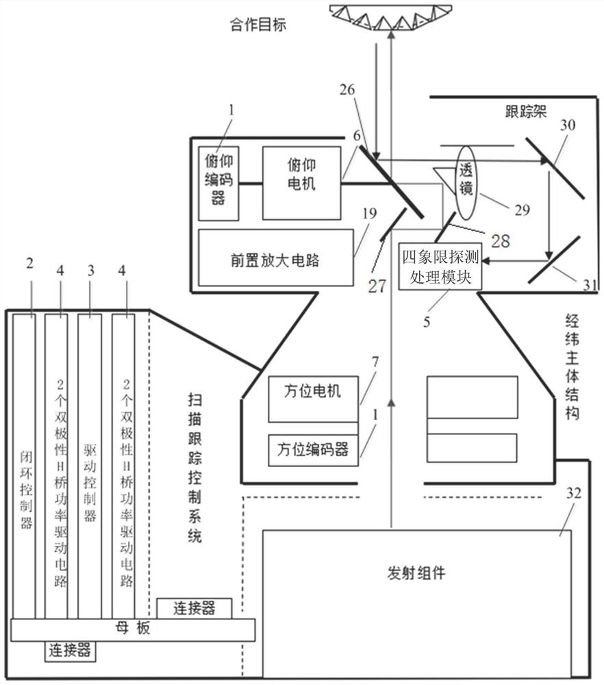
[0044] Such as figure 1 As shown, the present i...


PUM


Abstract

The invention relates to a laser radar for space rendezvous and docking. The laser radar comprises a transmitting assembly, a laser adjusting device, a shaft angle encoder, a four-quadrant detection processing module and a servo drive control module. The transmitting assembly transmits laser. The laser adjusting device obtains a laser echo signal. The axial angle encoder detects an azimuth axis angle value and a pitch axis angle value. The four-quadrant detection processing module determines a two-dimensional miss distance and a distance measurement value according to the energy of the laser echo signal in each quadrant, wherein the laser echo signal is obtained after focusing by a scanning reflector. The servo drive control module controls two stepping motors to drive the azimuth axis and the pitch axis to rotate according to the azimuth axis angle value, the pitch axis angle value and the two-dimensional miss distance, and then the scanning reflector is driven to conduct scanning and tracking. According to the invention, the four-quadrant detection processing module is utilized to realize staring tracking to obtain the two-dimensional miss distance, and extract the distance measurement value of the laser echo signal, so that a set of receiving optical system is saved, and a light and small laser radar is constructed.

Description


Claims


Application Information

Patent Timeline
Owner INST OF OPTICS & ELECTRONICS - CHINESE ACAD OF SCI
Why Eureka
Try Eureka