
Phase center compensation method based on signal incoming direction

A technology of phase center and compensation method, applied in space transmit diversity, radio transmission system, instruments, etc., can solve the problem that the accuracy is affected by noise, affects the communication bit error rate, radar measurement accuracy, navigation and positioning accuracy, limited estimation accuracy, etc.

Active Publication Date: 2021-06-01
NORTHWESTERN POLYTECHNICAL UNIV +1
View PDF8 Cites 0 Cited by
  • Summary
  • Abstract
  • Description
  • Claims
  • Application Information

AI Technical Summary

Problems solved by technology

[0003] Adding airspace adaptive signal processing technology to array digital beamforming will have a certain impact on the phase center of the received signal, which will eventually affect communication bit error rate, radar measurement accuracy, navigation positioning accuracy, etc. Therefore, when array digital beamforming A certain compensation method needs to be adopted. The commonly used methods include the input and output signal estimation signal distortion method and the training equalization filter method. However, in the case of a negative signal-to-noise ratio, the signal power is much lower than the noise, and the signal estimation compensation parameters are different. The accuracy is seriously affected by noise, the estimation accuracy is limited, and the compensation of the phase center is difficult to achieve high accuracy

Method used

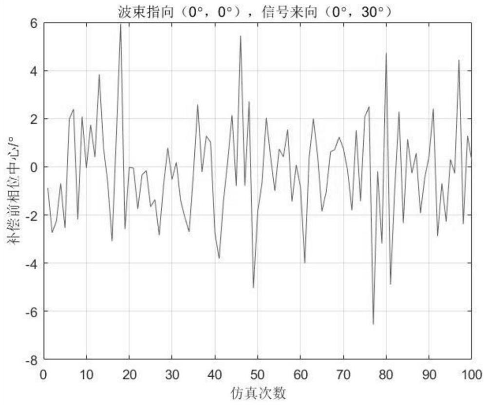
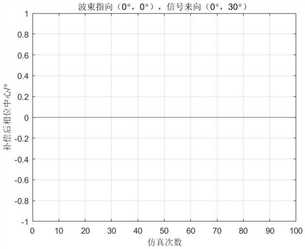
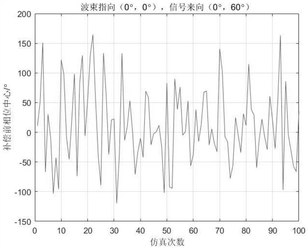

Image

  • Phase center compensation method based on signal incoming direction
  • Phase center compensation method based on signal incoming direction
  • Phase center compensation method based on signal incoming direction

Examples


Embodiment Construction

[0030] The present invention will be further described below in conjunction with the accompanying drawings and embodiments.

[0031] The technical solution adopted by the present invention to solve its technical problems comprises the following steps:

[0032] a) The receiver receives the signals of N array element planar arrays, and the position of each array element is (x n ,y n ), where n=1,2,...,N, the array elements are arranged at intervals of d=λ / 2, λ is the signal wavelength, and the received signal of the receiver is expressed as:

[0033]

[0034] Where M is the number of signals, a m is the steering vector of the mth signal, where m=1,2,...,M, s m (t) is the mth signal at time t, v(t) is the receiver thermal noise at time t, s m (t) and v(t) are statistically independent;

[0035] b) Calculate the covariance matrix R of the received signal as:

[0036] R=E[x(t)x H (t)]

[0037] c) Beam pointing to where θ d is the azimuth of the beam pointing, is the...


PUM


Abstract

The invention provides a phase center compensation method based on a signal coming direction, and aims to realize high-precision compensation on a signal phase center after an airspace adaptive signal processing technology is added into array digital beam forming.According to the invention, under the condition that the wave beam pointing direction is at any angle, according to the priori information of the signal incoming direction, a phase center error corresponding to the signal is calculated to realize phase center compensation. According to the invention, high-precision compensation of the signal phase center is realized after an airspace adaptive signal processing technology is added into array digital beam forming.

Description

technical field [0001] The invention relates to the field of array signal processing, in particular to a method for phase center compensation after array digital beam forming. Background technique [0002] With the continuous development of technologies such as array signal processing and digital beamforming, the application of array digital beamforming technology has attracted more and more attention. Array digital beamforming has the characteristics of high array gain and convenient beam index adjustment. It is widely used in communication systems, radar systems, navigation systems and other fields. The influence of array digital beamforming on the phase center of received signals is a key consideration. [0003] Adding airspace adaptive signal processing technology to array digital beamforming will have a certain impact on the phase center of the received signal, which will eventually affect communication bit error rate, radar measurement accuracy, navigation positioning ...

Claims


Application Information

Patent Timeline
Patent Type & Authority Applications(China)
IPC IPC(8): H04B7/08G01S7/02
CPCH04B7/0848H04B7/086H04B7/0897G01S7/02
Inventor 韩闯王伶谢坚陶明亮粟嘉汪跃先张兆林陈清浪丁立超宫延云范一飞邢自健
Owner NORTHWESTERN POLYTECHNICAL UNIV
Learn More