Edge deburring device for rock plate machining

A technology for edge deburring and rock slabs, which is applied to machine tools, grinding drive devices, metal processing equipment, etc. suitable for grinding the edges of workpieces, and can solve rock slab wear, low grinding efficiency, and low grinding precision of rock slabs, etc. question

Active Publication Date: 2021-06-04
高安常莹新型材料有限公司
View PDF5 Cites 4 Cited by
  • Summary
  • Abstract
  • Description
  • Claims
  • Application Information

AI Technical Summary

Problems solved by technology

[0004] In order to overcome the shortcomings of manual grinding, severe wear of rock slabs, low grinding efficiency, and low precision of grinding rock slabs, the technical problem of the present invention is to provide an edge for rock slab processing that can realize automatic grinding, does not require manual work, and is simple to operate Deburring device

Method used


Image

  • Edge deburring device for rock plate machining
  • Edge deburring device for rock plate machining
  • Edge deburring device for rock plate machining

Examples


Embodiment 1

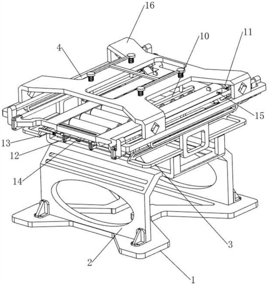
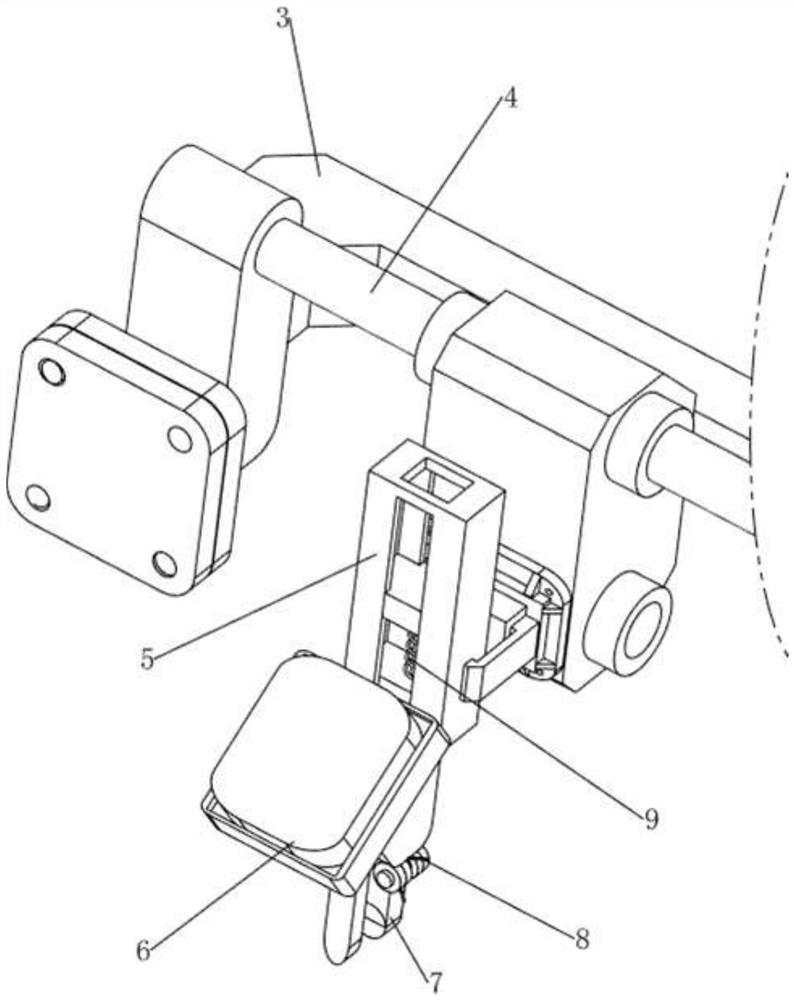
[0031] An edge deburring device for slate processing, such as Figure 1-4 As shown, it includes a base 1, a first support frame 2, a second support frame 3, a trackless cylinder 4, a fixed frame 5, a first grinding block 6, a sliding rod 7, a first torsion spring 8, a first compression spring 9, The loading mechanism 10 and the clamping mechanism 11 are connected with the first support frame 2 on the front and rear sides of the base 1, the second support frame 3 is connected between the first support frame 2, and the left and right sides of the second support frame 3 are connected with trackless The cylinder 4 and the trackless cylinder 4 are all slidably connected with a fixed frame 5, and the fixed frame 5 is slidably connected with a first grinding block 6, and the bottom of the first grinding block 6 is rotatably connected with a slide bar 7, and the slide bar 7 and First torsion springs 8 are arranged between the first grinding blocks 6, first compression springs 9 are ar...

Embodiment 2

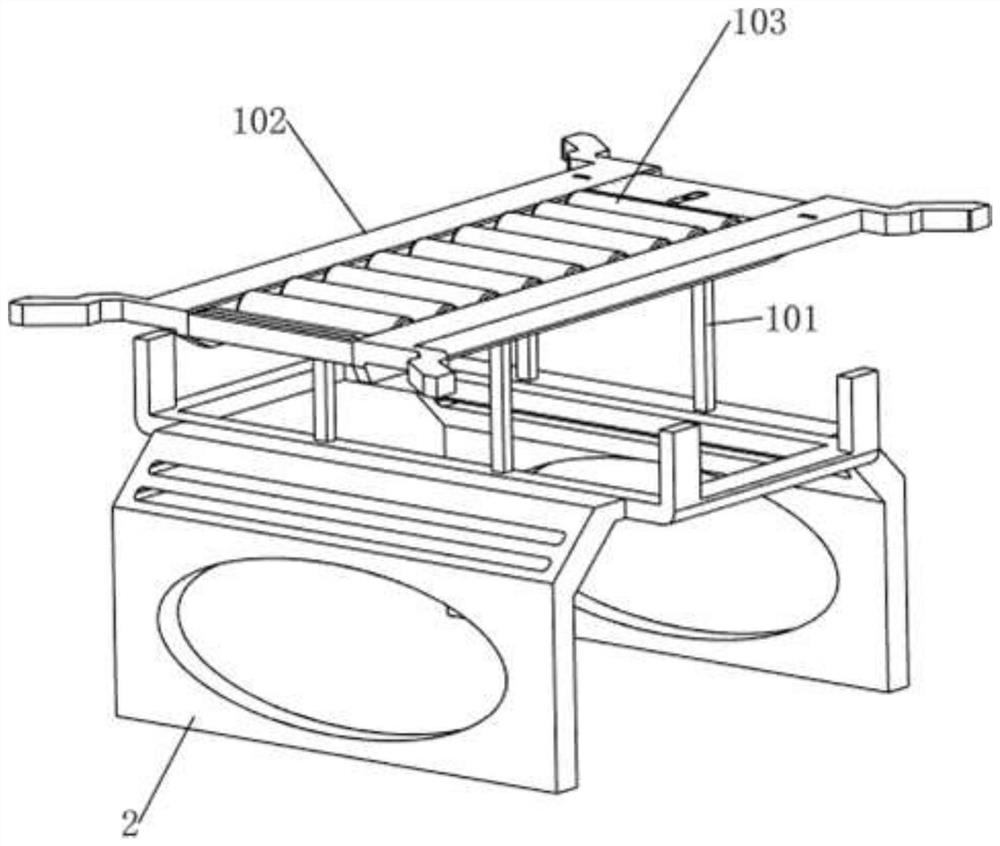
[0036] On the basis of Example 1, such as Figure 5-12 As shown, it also includes a blocking mechanism 12. The blocking mechanism 12 includes a clamping rod 121, a baffle 122 and a second compression spring 123. The front side of the support plate 102 is slidably connected to the baffle 122. A second compression spring 123 is provided between the side and the support plate 102 , and a locking rod 121 is provided at the bottom of the baffle plate 122 .

[0037] The original state of the baffle plate 122 is the state of moving upwards. When people discharge the material, the baffle plate 122 and the clamping rod 121 are moved downward, so that the second compression spring 123 is compressed, and when the material is pushed backward and separated from the baffle plate 122 , under the action of the second compression spring 123, the baffle plate 122 and the clamping rod 121 are driven to move upward and reset, so that the position of the material can be limited.

[0038] Also inc...


PUM


Abstract

The invention relates to a deburring device, in particular to an edge deburring device for rock plate machining. According to the edge deburring device for rock plate machining, automatic grinding can be achieved, manual operation is not needed, and operation is easy. According to the technical scheme, the edge deburring device for rock plate machining comprises a base, first supporting frames, a second supporting frame, trackless air cylinders and fixing frames, the first supporting frames are connected to the two sides of the base, the second supporting frame is connected between the first supporting frames, the trackless air cylinders are connected to the two sides of the second supporting frame, and the fixing frames are slidably connected to the trackless air cylinders. Through cooperation of a loading mechanism and a clamping mechanism, automatic deburring can be conducted on the edge of a rock plate, manual grinding is not needed, and time and labor are saved.

Description

technical field [0001] The invention relates to a burring device, in particular to an edge deburring device for rock slab processing. Background technique [0002] In the process of making rock slabs, because there are burrs on the rock slabs, edge grinding is required. Now grinding is usually done manually. At present, there are two commonly used manual grinding methods: one is to use sandpaper for grinding, and the other is Grind with a file. However, when sanding paper is used for grinding, the rock plate is severely worn, and the grinding efficiency is not high, and the sanding paper is disposable, and the cost is relatively high. When using a file for grinding, it is easy to cause low precision in grinding the rock slab due to uneven force, and the contact area between the file and the rock slab is small, and the hardness of the file is relatively large, so brittle deformation is likely to occur during grinding, which makes the rock slab wear seriously. [0003] There...

Claims


Application Information

Patent Timeline
Patent Type & Authority Applications(China)
IPC IPC(8): B24B9/06B24B27/00B24B41/00B24B41/06B24B47/00B24B47/16B24B47/22
CPCB24B9/06B24B27/0076B24B41/06B24B47/00B24B47/22B24B47/16B24B27/0069B24B41/005
Inventor 全春辉
Owner 高安常莹新型材料有限公司
Why Eureka
Try Eureka