
Connection adapter for turbomachine and turbomachine

A technology of adapters and turbines, applied in the direction of machines/engines, gas turbine devices, mechanical equipment, etc.

Inactive Publication Date: 2021-06-04
MAN ENERGY SOLUTIONS SE
View PDF0 Cites 0 Cited by
  • Summary
  • Abstract
  • Description
  • Claims
  • Application Information

AI Technical Summary

Problems solved by technology

this is disadvantageous

Method used


Image

  • Connection adapter for turbomachine and turbomachine
  • Connection adapter for turbomachine and turbomachine
  • Connection adapter for turbomachine and turbomachine

Examples


Embodiment Construction

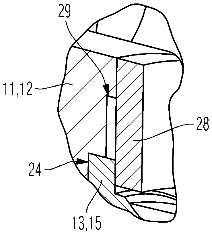
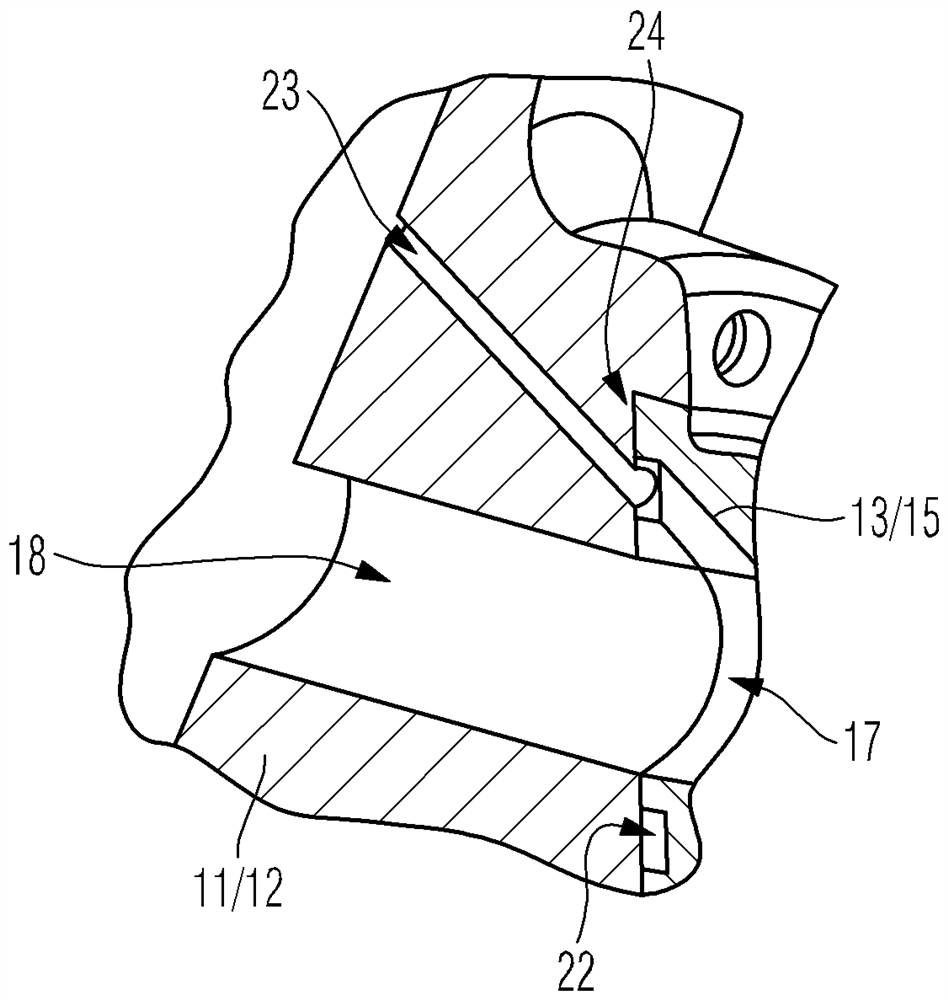
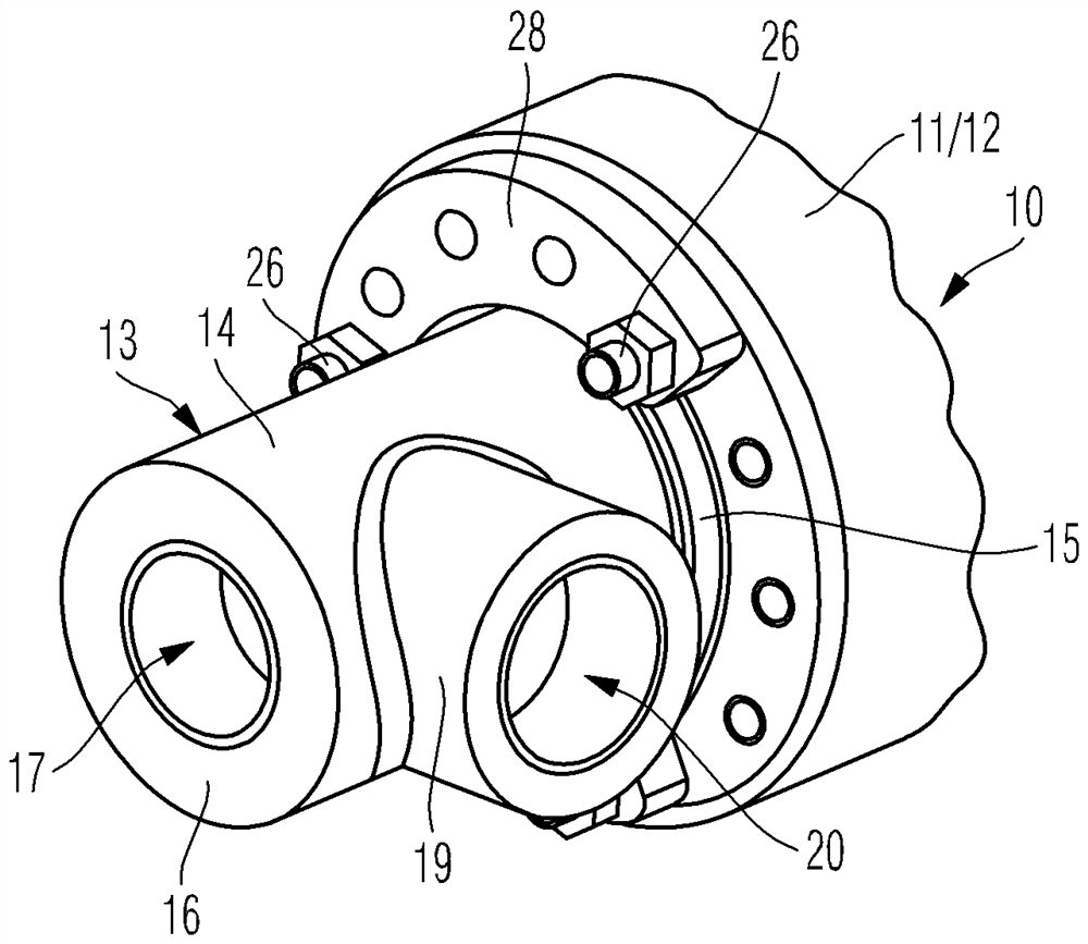
[0018] figure 1 A perspective excerpt of a turbine 10 according to the invention is shown in the region of the turbine inflow housing 11 of the turbine 10, wherein a connection flange 12 is formed on the turbine inflow housing 11 and a connection adapter 13 according to the invention is mounted on the connection flange 12 on.

[0019] The connection adapter 13 comprises a main body 14 with a first axial section 15 connecting the connection adapter 13 to the connection flange 12 of the turbine housing 11 and oppositely positioned to connect a not shown dry cleaning agent feed line. to the second axial section 16 of the connection adapter 13 . The two axial sections 15 , 16 can also be referred to as axial end sections. It is located at opposite axial ends of the main body 14 .

[0020] Via the first axial section 15 of the main body 13 the connection adapter 13 is connected in this way to the connection flange 12 and correspondingly to the turbine housing 11 in the following...


PUM


Abstract

A connection adapter for a turbomachine is disclosed, the connection adapter is connectable to a turbomachine housing of the turbomachine, a feed line for a cleaning agent can be connected to the connection adapter, and the connection adapter has a body, wherein the body comprises a first axial section and an opposing second axial section, the connection adapter may be connected to the turbine housing in such a manner that the dry detergent conduit extends coaxially to the turbine rotor of the turbine, the body comprises a radial section connecting the liquid detergent feed line to the connection adapter, the liquid detergent conduit of the body is formed in this radial section, and the radial section is coupled to a groove formed on the first axial section and extending in a circumferential direction around the dry cleaning agent conduit via at least one longitudinal conduit extending in a radial direction and following the dry cleaning agent conduit radially outside.

Description

technical field [0001] The invention relates to a connection adapter for a turbomachine. Furthermore, the invention relates to a turbomachine with a connection adapter. Background technique [0002] It is known from practice to clean the turbine and the turbine diffuser of the exhaust-gas turbocharger, ie the turbine rotor of the turbine, at defined time intervals during operation. For this purpose, two different methods are known in principle, wet cleaning with liquids, in particular water, and dry cleaning with granules. For this purpose, cleaning agent needs to be fed to the turbine, ie to the turbine housing, in order to be able to guide the corresponding cleaning agent for cleaning the turbine, in particular to the turbine rotor and the turbine diffuser of the turbine, in a defined manner. [0003] Furthermore, it is known from practice that the turbine housing of the turbine consists of a turbine inflow housing and a turbine outflow housing, wherein the turbine inflo...

Claims


Application Information

Patent Timeline
IPC IPC(8): F01D25/24F01D25/00
CPCF01D25/243F01D25/002F01D25/24F01D9/02F02C6/12B08B3/04B08B7/00F05D2220/40F05D2260/31
Inventor J·施特克尔M·卡尔希施密德O·勒夫莱因
Owner MAN ENERGY SOLUTIONS SE
Learn More