Quasi-in-situ test method for crystal structure evolution in pulse current synchronous loading stretching
A technology of crystal structure and pulse current, applied in the direction of applying stable tension/pressure to test the strength of materials, measuring devices, instruments, etc., can solve problems such as inability to perform in-situ testing, and achieve the effect of acquisition
- Summary
- Abstract
- Description
- Claims
- Application Information
AI Technical Summary
Problems solved by technology
Method used
Image
Examples
Embodiment 1
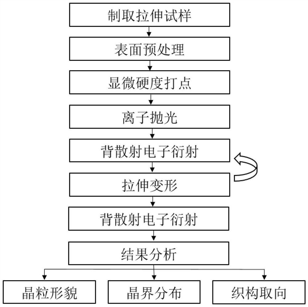
[0062] as attached figure 1 As shown, a quasi-in-situ test method for crystal structure evolution in pulse current synchronous loading and stretching of nickel-based superalloy, the method includes the following steps:
[0063] Step 1, prepare a tensile sample:
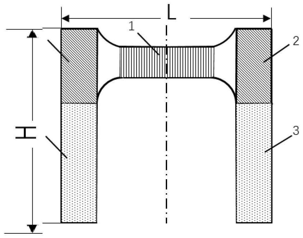
[0064] A tensile sample is cut from a nickel-based superalloy rolled plate, and the shape of the tensile sample is an inverted "U" shape. The length L of the tensile sample is 16.8 mm, the width H is 12.3 mm, and the thickness D is 1 mm. The bottom of the "U" shape of the tensile sample is the main deformation area of the sample, and this deformation area is defined as gauge length section 1 of the tensile sample. as attached image 3 As shown, the length l of the gauge section of the tensile sample is 5 mm, the width h is 2 mm, and the thickness d is 1 mm.
[0065] The two ends of the bottom of the "U" shape of the tensile sample are the clamping ends 2 of the tensile sample, and the open ends of the "U" shape...
Embodiment 2
[0099] as attached figure 1 As shown, a quasi-in-situ testing method for crystal structure characteristics in a nickel-based superalloy pulse current synchronous loading and stretching process, the method includes the following steps:
[0100] Step 1, prepare a tensile sample:
[0101]Cut a tensile sample from a nickel-based superalloy rolled plate, the shape of the tensile sample is an inverted "U" shape; the length L of the tensile sample is 16.8mm, the width H is 12.3mm, and the thickness is D 1mm. The bottom of the "U" shape of the tensile sample is the main deformation area of the sample, and this deformation area is defined as gauge length section 1 of the tensile sample. as attached image 3 As shown, the length l of the gauge section of the tensile sample is 5 mm, the width h is 1 mm, and the thickness d is 1 mm.
[0102] The two ends of the bottom of the "U" shape of the tensile sample are the clamping ends 2 of the tensile sample, and the open ends of the "U" ...
Embodiment 3
[0136] as attached figure 1 As shown, a quasi-in-situ testing method for crystal structure characteristics in a nickel-based superalloy pulse current synchronous loading and stretching process, the method includes the following steps:
[0137] Step 1, prepare a tensile sample:
[0138] Cut a tensile sample from a nickel-based superalloy rolled plate, the shape of the tensile sample is an inverted "U" shape; the length L of the tensile sample is 16.8mm, the width H is 12.3mm, and the thickness is D 1mm. The bottom of the "U" shape of the tensile sample is the main deformation area of the sample, and this deformation area is defined as gauge length section 1 of the tensile sample. as attached image 3 As shown, the length l of the gauge section of the tensile sample is 5 mm, the width h is 1 mm, and the thickness d is 1 mm.
[0139] The two ends of the bottom of the "U" shape of the tensile sample are the clamping ends 2 of the tensile sample, and the open ends of the "U"...
PUM
| Property | Measurement | Unit |
|---|---|---|
| Length | aaaaa | aaaaa |
| Width | aaaaa | aaaaa |
| Thickness | aaaaa | aaaaa |
Abstract
Description
Claims
Application Information
 - R&D
- Intellectual Property
- Life Sciences
- Materials
- Tech Scout
- Unparalleled Data Quality
- Higher Quality Content
- 60% Fewer Hallucinations
Browse by: Latest US Patents, China's latest patents, Technical Efficacy Thesaurus, Application Domain, Technology Topic, Popular Technical Reports.
© 2025 PatSnap. All rights reserved.Legal|Privacy policy|Modern Slavery Act Transparency Statement|Sitemap|About US| Contact US: help@patsnap.com


