Supercharge Your Innovation With Domain-Expert AI Agents!

Direct drive motor structure and motor

A direct-drive motor and motor shaft technology, applied in the direction of magnetic circuit shape/style/structure, winding conductor shape/style/structure, electric components, etc., can solve permanent magnet motor torque ripple, speed fluctuation, cogging Large torque and other problems, to achieve the effect of easy connection and reduce cogging torque

Active Publication Date: 2021-06-04
INST OF INTELLIGENT MFG TECH JITRI
View PDF3 Cites 0 Cited by
  • Summary
  • Abstract
  • Description
  • Claims
  • Application Information

AI Technical Summary

Problems solved by technology

[0007] Therefore, the technical problem to be solved by the present invention is that the traditional permanent magnet synchronous motor has the disadvantage of large cogging torque, and the cogging torque will cause the torque ripple of the permanent magnet motor, and then cause the speed fluctuation

Method used


Image

  • Direct drive motor structure and motor
  • Direct drive motor structure and motor
  • Direct drive motor structure and motor

Examples


Embodiment 1

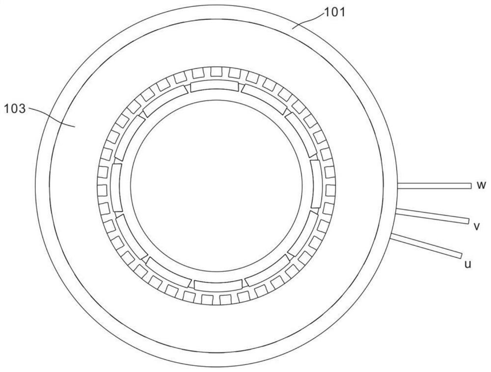
[0048] refer to Figure 1~5 , this embodiment provides a direct drive motor structure, including,

[0049] The stator component 100, the stator component 100 includes an outer ring 101 and a stator punching sheet 102 laminated in the outer ring 101;

[0050] The rotor component 200 , the rotor component 200 is disposed inside the stator component 100 , and the rotor component 200 includes a rotor core 201 and a magnetic steel 202 embedded outside the rotor core 201 .

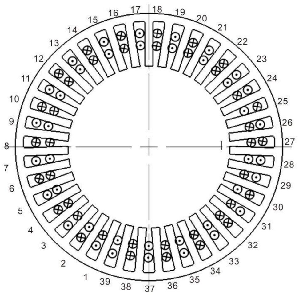
[0051] The stator stamping 102 includes a slot yoke 102a, stamping slots 102b and spacers 102c, and the stamping slots 102b and spacers 102c are arranged alternately inside the slot yoke 102a.

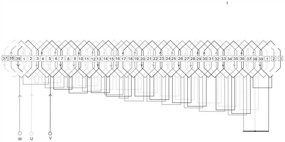
[0052]It should be noted that punching grooves 102b are provided on the groove yoke 102a, and spacers 102c are left between the punching grooves 102b to make the boundaries between the punching grooves 102c clear. The winding mode of the winding between the punching slots 102b is changed by taking the spacer bar 102c a...

Embodiment 2

[0069] refer to Figure 6-11 , this embodiment provides a direct-drive motor, including the above-mentioned structure of a direct-drive motor, and also includes,

[0070] A motor shaft 300, a ring sleeve 301 is fixed on the motor shaft 300, and an inner groove 302 is arranged between the ring sleeve 301 and the motor shaft 300;

[0071] A first through hole 303 is provided on the circumferential surface of the ring sleeve 301, a slot 304 is provided on the motor shaft 300, and the position of the first through hole 303 corresponds to the position of the slot 304;

[0072] The motor shaft 300 is disposed inside the rotor core 201 and connected to the rotor core 201 through a connector 400 .

[0073] The position of the first through hole 303 corresponds to the position of the slot 304 , which means that the projection positions of the first through hole 303 and the slot 304 coincide with each other along the axial direction of the motor shaft.

[0074] The plug connector 400 ...


PUM


Abstract

The invention discloses a direct drive motor structure and a motor. The structure comprises a stator part including an outer ring and a stator punching sheet laminated in the outer ring, and a rotor part arranged in the stator part. The rotor part comprises a rotor iron core and magnetic steel embedded in the outer side of the rotor iron core. The direct drive motor comprises a motor shaft, a ring sleeve is fixed on the motor shaft, and an inner groove is arranged between the ring sleeve and the motor shaft; a first through hole is formed in the circumferential surface of the ring sleeve, a slot is formed in the motor shaft, and the first through hole corresponds to the slot in position; and the motor shaft is arranged on the inner side of the rotor iron core and is connected with the rotor iron core through a plug connector. According to the direct drive motor structure disclosed by the invention, a winding wire adopts a short-pitch asymmetric winding mode so that a cogging torque is effectively reduced, a slot fullness rate is about 70%, and an overload is more than 3 times; and according to the direct drive motor, the motor shaft can be conveniently connected with the rotor inner core.

Description

technical field [0001] The invention relates to the technical field of direct drive motors, in particular to a direct drive motor structure and a motor. Background technique [0002] Frameless direct drive motor is a new type of torque motor, which is specially designed for applications requiring small size, light weight, low inertia, compact structure and high power. It has broad application prospects in the field of joints, unmanned aerial vehicle propulsion and guidance systems, and other applications. The direct drive motor has a large hollow aperture for easy wiring. In the pursuit of product lightweight design principles, frameless direct drive motors have incomparable advantages. [0003] For the high-precision industry, the traditional permanent magnet synchronous motor has the disadvantage of large cogging torque, which will cause the torque ripple of the permanent magnet motor, and then lead to speed fluctuations. Torque ripple will also cause vibration and nois...

Claims


Application Information

Patent Timeline
IPC IPC(8): H02K1/27H02K1/30H02K3/28H02K1/16
CPCH02K1/276H02K1/30H02K3/28H02K1/165H02K2213/03
Inventor 罗雪峰骆敏舟宋近府戈子康
Owner INST OF INTELLIGENT MFG TECH JITRI
Features
  • R&D
  • Intellectual Property
  • Life Sciences
  • Materials
  • Tech Scout
  • Unparalleled Data Quality
  • Higher Quality Content
  • 60% Fewer Hallucinations
Learn More