Video code rate control method and device, electronic equipment and storage medium
A code rate control and video technology, applied in the direction of digital video signal modification, electrical components, image communication, etc., can solve the problem that the code rate cannot be effectively reduced, and achieve the effect of reducing the code rate
- Summary
- Abstract
- Description
- Claims
- Application Information
AI Technical Summary
Problems solved by technology
Method used
Image

Examples
Embodiment 1
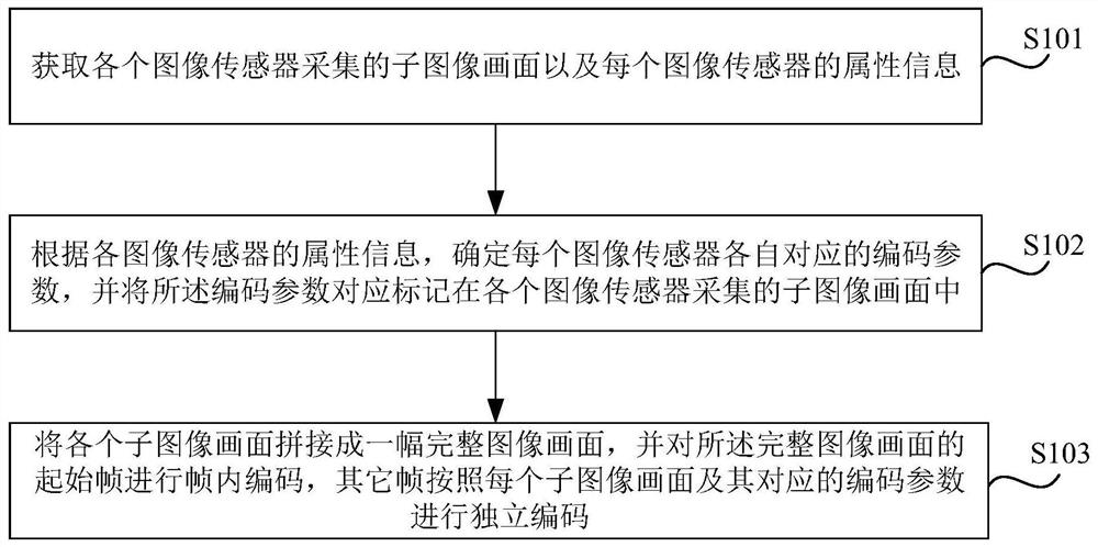
[0025] figure 1 It is a flow chart of the video bit rate control method provided in Embodiment 1 of the present invention. This embodiment is applicable to the case of encoding video pictures collected by a multi-purpose splicing device, and the method can be executed by a video bit rate control device. The device can be implemented in the form of software and / or hardware, and can be integrated on electronic equipment, such as multi-purpose splicing equipment.
[0026] Such as figure 1 As shown, the video code rate control method specifically includes:
[0027] S101. Acquire sub-image frames captured by each image sensor and attribute information of each image sensor.
[0028] In the embodiment of the present invention, the multi-purpose splicing device includes a plurality of image sensors for real-time acquisition of image frames, so it is necessary to obtain the sub-image frames collected by each image sensor and the attribute information of each image sensor in real time...
Embodiment 2
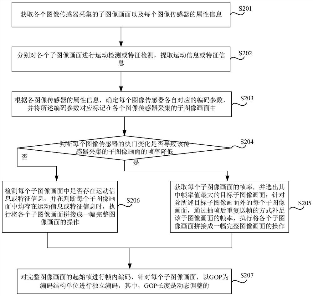
[0035] figure 2 It is a schematic flow chart of a video bit rate control method in the second implementation of the present invention. This embodiment is optimized on the basis of the above-mentioned embodiments. Refer to figure 2 , the method specifically includes:
[0036] S201. Obtain sub-image frames captured by each image sensor and attribute information of each image sensor.
[0037] S202. Perform motion detection or feature detection on each sub-image frame respectively, and extract motion information or feature information.
[0038] Optionally, motion detection can be performed based on the frame difference method. Specifically, the difference image is obtained by subtracting the corresponding pixel values of adjacent frame images, and then the difference image is binarized. When the pixel value change is less than a predetermined threshold, it can be considered as a background pixel; if the pixel value of the image area changes greatly, it can be considered that...
Embodiment 3
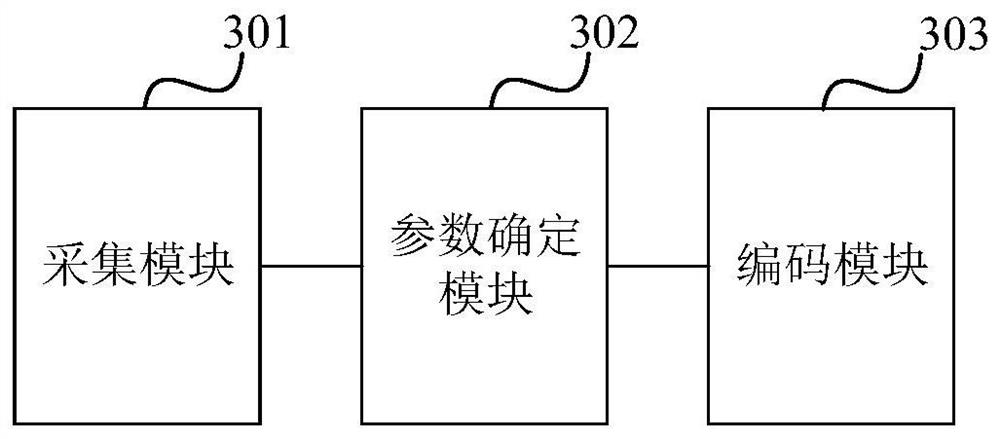
[0054] image 3 It is a schematic structural diagram of a video bit rate control device in Embodiment 3 of the present invention. The device is configured in a multi-purpose splicing device, and the multi-purpose splicing device includes a plurality of image sensors for collecting image frames. Such as image 3 As shown, the device includes:
[0055] The collection module 301 is used to obtain the sub-image pictures collected by each image sensor and the attribute information of each image sensor;
[0056] The parameter determining module 302 is used to determine the encoding parameters corresponding to each image sensor according to the attribute information of each image sensor, and correspondingly mark the encoding parameters in the sub-image frames collected by each image sensor;
[0057] The coding module 303 is used to splice each sub-image frame into a complete image frame, perform intra-frame coding on the start frame of the complete image, and perform independent co...
PUM
 Abstract
Description
Claims
Application Information
 - R&D
- Intellectual Property
- Life Sciences
- Materials
- Tech Scout
- Unparalleled Data Quality
- Higher Quality Content
- 60% Fewer Hallucinations
Browse by: Latest US Patents, China's latest patents, Technical Efficacy Thesaurus, Application Domain, Technology Topic, Popular Technical Reports.
© 2025 PatSnap. All rights reserved.Legal|Privacy policy|Modern Slavery Act Transparency Statement|Sitemap|About US| Contact US: help@patsnap.com