Method and apparatus for concatenated channel coding with variable code rate and coding gain in a data transmission system

a data communication system and variable code rate technology, applied in the field of coding methods and apparatuses, can solve the problems of more complex code implementation and more complex code, and achieve the effects of reducing complexity, cost, size and power consumption, and efficient coding data

Inactive Publication Date: 2005-05-12
TUMBLEWEED HLDG LLC +1
View PDF10 Cites 22 Cited by
  • Summary
  • Abstract
  • Description
  • Claims
  • Application Information

AI Technical Summary

Benefits of technology

[0017] The present invention is a novel method and apparatus for efficiently coding data in a data transmission system. The inventive concatenated channel coding technique is well suited for small or variable size packet data transmission systems. The technique may also be adapted for use in a continuous mode data transmission system. The method and apparatus reduces the complexity, cost, size and power consumption typically associated with the prior art channel coding methods and apparatuses, while still a

Problems solved by technology

The higher the dmin, the more complex the code usually is.
But usually, the higher the dmi

Method used


Image

  • Method and apparatus for concatenated channel coding with variable code rate and coding gain in a data transmission system
  • Method and apparatus for concatenated channel coding with variable code rate and coding gain in a data transmission system
  • Method and apparatus for concatenated channel coding with variable code rate and coding gain in a data transmission system

Examples


Embodiment Construction

[0033] Throughout this description, the preferred embodiment and examples shown should be considered as exemplars, rather than as limitations on the present invention.

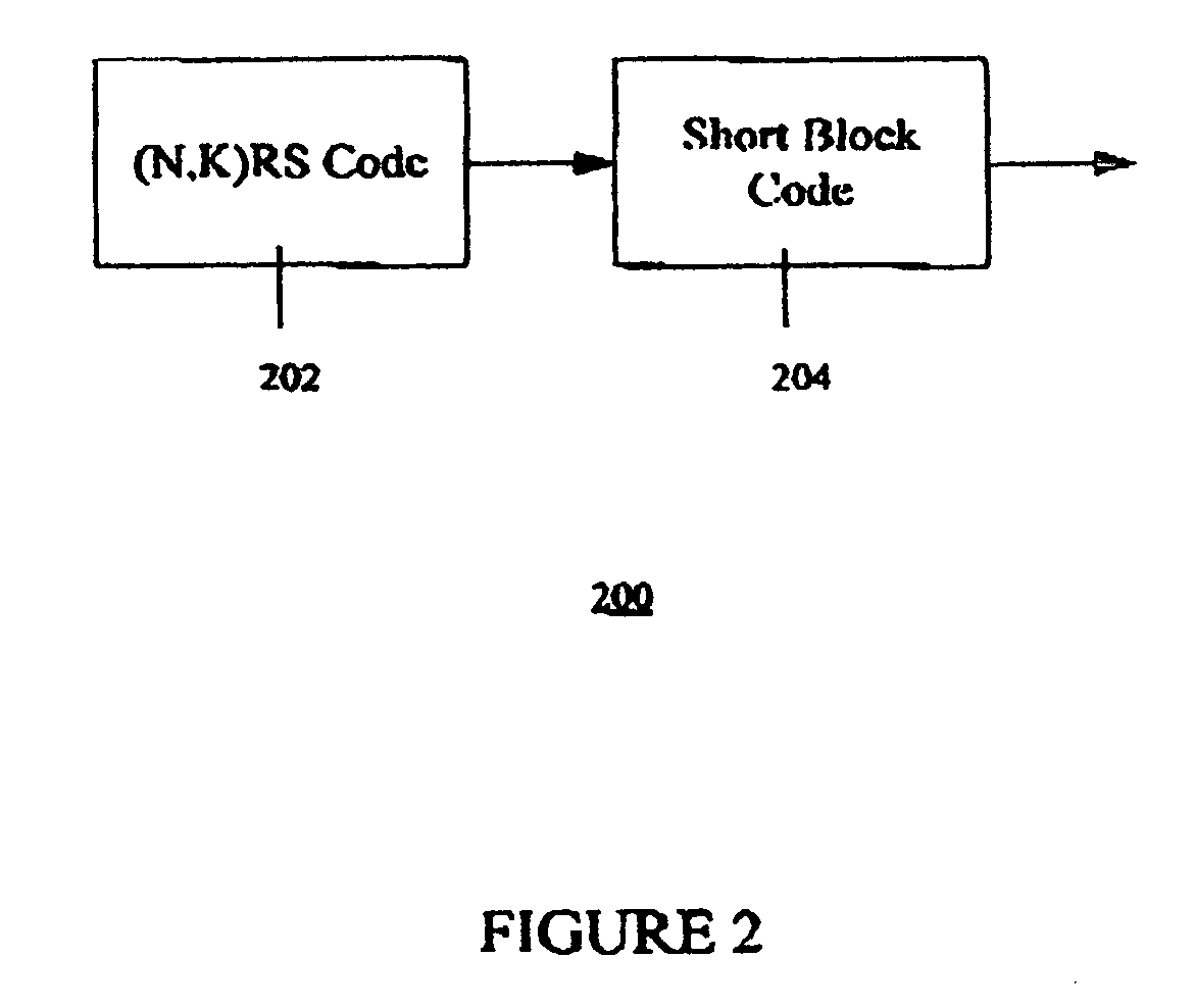
[0034] One significant advantage of the present concatenated coding technique is that it not only eliminates the need for a symbol interleaver between the outer and inner codes, but it also enjoys drastically reduced implementation complexity of the inner code Viterbi decoder. That is, the Viterbi decoder used to implement the inner code is much less complex than those required by the prior art approaches. Viterbi coders / decoders are well known in the art and are described in much more detail in a text by Shu Lin and Daniel Costello, Jr., entitled “Error Control Coding, Fundamentals and Applications”, published by Prentice Hall in 1983, the entire text of which is hereby incorporated by reference herein for its teachings on error control coding.

[0035] The present inventive concatenation technique does not require use...


PUM


Abstract

A novel method and apparatus for efficiently coding and decoding data in a data transmission system is described. A concatenated coding scheme is presented that is easily implemented, and that provides acceptable coding performance characteristics for use in data transmission systems. The inventive concatenated channel coding technique is well suited for small or variable size packet data transmission systems. The technique may also be adapted for use in a continuous mode data transmission system. The method and apparatus reduces the complexity, cost, size and power consumption typically associated with the prior art channel coding methods and apparatuses, while still achieving acceptable coding performance. The present invention advantageously performs concatenated channel coding without the necessity of a symbol interleaver. In addition, the present invention is simple to implement and thereby consumes much less space and power that do the prior art approaches. The present invention not only eliminates the need for a symbol interleaver between the outer and inner codes, but it also enjoys a drastically reduced implementation complexity of the inner code Viterbi decoder. The preferred embodiment of the present invention comprises an inner code having short length block codes derived from short constraint length convolutional codes utilizing trellis tailbiting and a decoder comprising four four-state Viterbi decoders having a short corresponding maximum length. The inner code preferably comprises short block codes derived from four-state (i.e., constraint length 3), nonsystematic, punctured and unpunctured convolutional code. One significant advantage of the preferred embodiment of the present concatenated coding technique is that packet data transmission systems can be designed to have variable coding gains and coding rates.

Description

CROSS-REFERENCE TO RELATED APPLICATIONS [0001] This application is a continuation-in-part of U.S. application Ser. No. 09 / 471,295, filed Dec. 24, 1999, entitled “Method and Apparatus for Concatenated Channel Coding in a Data Transmission System”, hereby incorporated by reference herein for its teachings on communication systems. This application is related to commonly-assigned U.S. Pat. No. 6,016,311, issued Jan. 18, 2000 and entitled “An Adaptive Time Division Duplexing Method and Apparatus for Dynamic Bandwidth Allocation within a Wireless Communication System”, and commonly-assigned co-pending application Ser. No. 09 / 316,518, filed May 21, 1999 entitled “Method and Apparatus for Allocating Bandwidth in a Wireless Communication System”, both references hereby incorporated by reference herein for their teachings on communication systems.BACKGROUND OF THE INVENTION [0002] 1. Field of the Invention [0003] This invention relates to coding methods and apparatuses, and more particularly...

Claims


Application Information

Patent Timeline
IPC IPC(8): H03M13/15H03M13/23H03M13/29H03M13/41H03M13/45H04L1/00
CPCH03M13/1505H03M13/6561H03M13/155H03M13/19H03M13/23H03M13/253H03M13/256H03M13/29H03M13/2906H03M13/293H03M13/2936H03M13/2996H03M13/3944H03M13/41H03M13/413H03M13/618H03M13/635H03M13/6362H03M13/1515
Inventor GUPTA, ALOK KUMAR
Owner TUMBLEWEED HLDG LLC
Why Eureka
Try Eureka