

Moving picture coding method, moving picture decoding method and program
a coding method and picture technology, applied in the field of coding and decoding methods for moving pictures, can solve problems such as degrading the uniqueness of films produced, and achieve the effect of efficient coding without impairing the quality of pictures
- Summary
- Abstract
- Description
- Claims
- Application Information
AI Technical Summary
Benefits of technology
Problems solved by technology
Method used
Image

Examples
first embodiment
100>
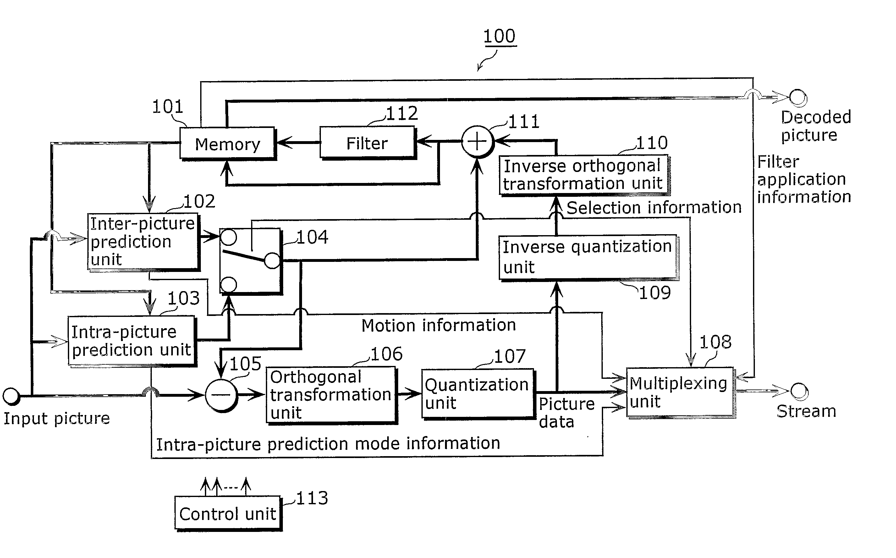
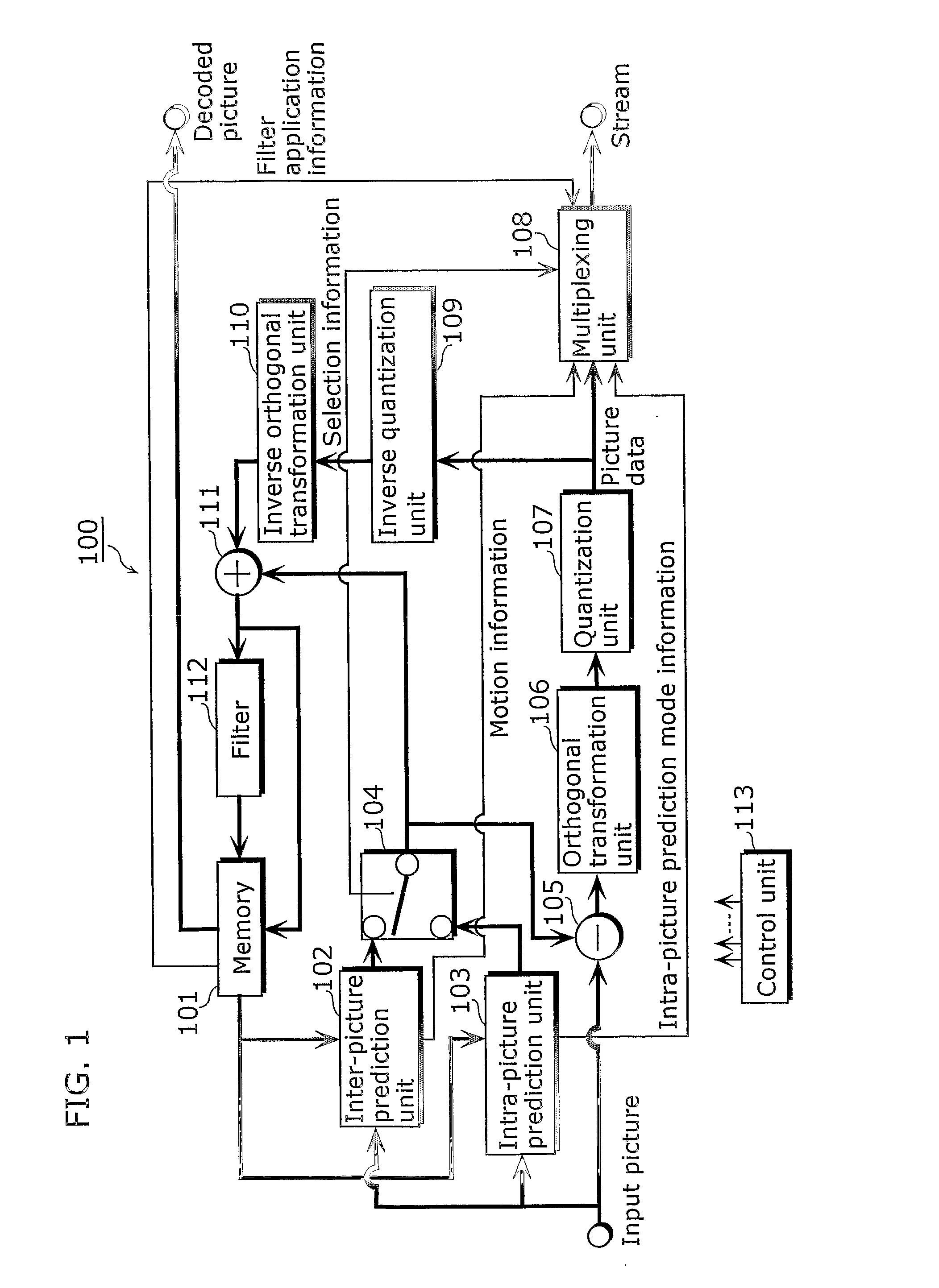
[0064]FIG. 1 is a block diagram showing the structure of the picture coding apparatus according to the first embodiment of the present invention. As shown in the diagram, the picture coding apparatus 100 is composed of a memory 101, an inter-picture prediction unit 102, an intra-picture prediction unit 103, a switch 104, a subtracter 105, an orthogonal transformation unit 106, a quantization unit 107, a multiplexing unit 108, an inverse quantization unit 109, an inverse orthogonal transformation unit 110, an adder 111, a filter 112 and a control unit 113.
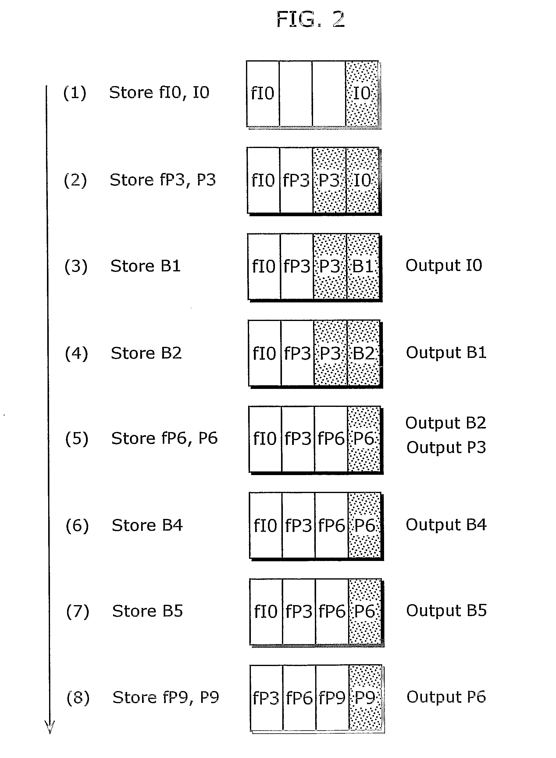
[0065] The memory 101 stores pictures both unfiltered and filtered by the filter 112. The pictures filtered by the filter 112 are used as reference pictures while the pictures that are not filtered are used as output pictures. The film grains are reduced for the reference pictures so that coding efficiency is improved. The film grains are left for the output pictures so that the quality of films is not degraded.
[0066] The inte...
second embodiment
[0126] The structures of the picture coding apparatus 100 and the picture decoding apparatus 200 according to the first embodiment are for the case in which the pictures are rearranged for display as seen in the picture alignments for prediction shown in FIGS. 18 and 19. The present embodiment describes the picture coding apparatus and the picture decoding apparatus for a case of using the picture alignment for prediction without such rearrangement.
[0127]FIG. 9 is a block diagram showing the structure of the picture coding apparatus according to the present embodiment. The picture coding apparatus 100a in the diagram stores only filtered pictures instead of storing both filtered and unfiltered pictures in the memory 101 and has an additional switch 114, which are different from the picture coding apparatus 100 shown in FIG. 1. The following focuses on the differences while the description for the similar points is abbreviated here.
[0128] The memory 101 stores a filtered picture as...
third embodiment
[0140] Furthermore, the processing illustrated in the above embodiment can be carried out easily in an independent computer system by recording a program for realizing the picture coding method described in the above embodiments onto a recording medium such as a flexible disk or the like.
[0141]FIGS. 12A, 12B and 12C are illustrations of a recording medium, on which a program for carrying out the picture coding method described in the first and second embodiments in the computer system is recorded.
[0142]FIG. 12B shows a full appearance of a flexible disk FD, its structure at cross section and a full appearance of the disk itself FD as a main body of a recording medium whereas FIG. 12A shows an example of a physical format of the flexible disk FD.
[0143] The disk FD is contained in a case F with a plurality of tracks Tr formed concentrically from the periphery to the inside on the surface of the disk FD, and each track is divided into 16 sectors Se in the angular direction. Thus, th...
PUM
 Abstract
Description
Claims
Application Information