Detachable combined type intelligent sound box

A smart speaker, combined technology, applied in the directions of loudspeakers, transducer shells/cabinets/brackets, frequency/directional characteristic devices, etc., can solve the problems of cumbersome use and inability to identify

Active Publication Date: 2021-06-04
SHENZHEN BAITAI IND CO LTD
View PDF6 Cites 1 Cited by
  • Summary
  • Abstract
  • Description
  • Claims
  • Application Information

AI Technical Summary

Problems solved by technology

[0006] In order to solve the problem of cumbersome use caused by not being able to identify which device needs to be connected, this application provides a detachable combined smart speaker

Method used


Image

  • Detachable combined type intelligent sound box
  • Detachable combined type intelligent sound box
  • Detachable combined type intelligent sound box

Examples


Embodiment 1

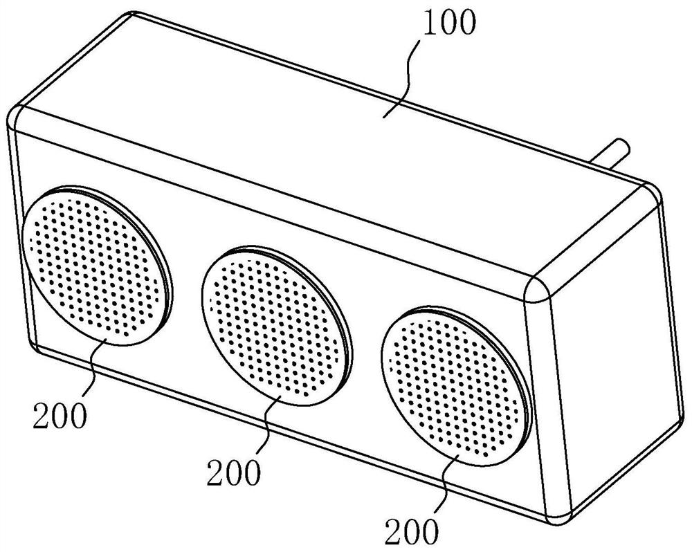
[0049] Embodiment 1: A detachable combined smart speaker, such as figure 1 As shown, the main box 100 and three sub-boxes 200, wherein the number of the sub-boxes 200 can be any number, but not limited to three, three are taken as an example for illustration in this embodiment.

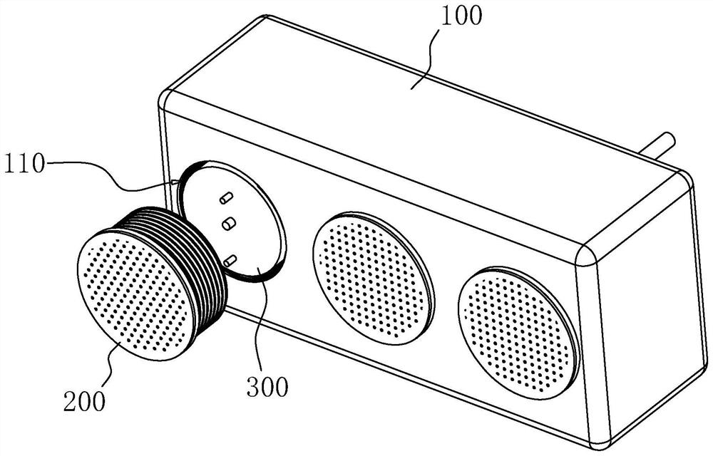
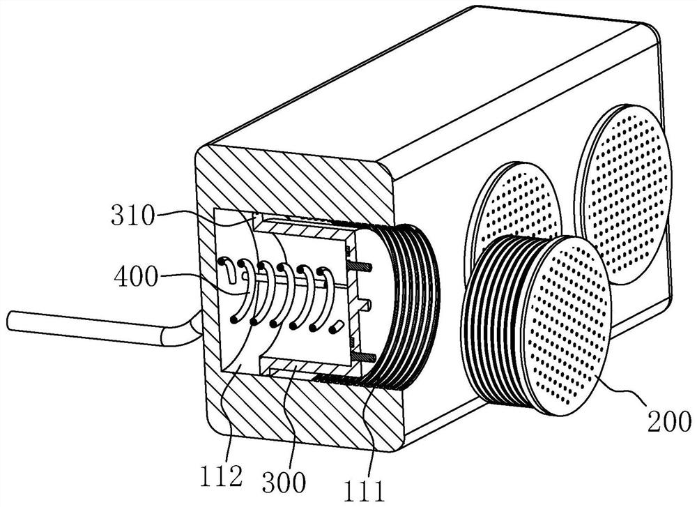
[0050] refer to figure 2 and image 3 , three threaded connection holes 110 are provided on the positive end face of the main box body 100. The threaded connection hole 110 includes a threaded section 111 and a light hole section 112. The inner end of the connection hole 110 . On the light hole section 112, a sliding seat 300 is slidably installed, and an annular convex rib 310 is arranged on the outer wall of one end of the sliding seat 300 facing the bottom of the threaded connection hole 110, and an annular rib 310 is arranged on the outer circumference of the annular convex rib 310. 111 suitable external thread.

[0051] A compression spring 400 is arranged between the sliding seat 300 and th...

Embodiment 2

[0067] Embodiment 2: as Figure 8 and Figure 9 As shown, the difference from Embodiment 1 is that the main box body 100 is provided with three sockets 130 for inserting the secondary box body 200 , and a push-type socket for clamping the secondary box body 200 is provided in the socket 130 . As for the automatic pop-up structure 500, one push-type automatic pop-up structure 500 is used as an example in this embodiment, but it is not limited to one.

[0068] refer to Figure 9 and Figure 10 The push-type automatic pop-up structure 500 includes a sliding block 510, a return spring 520, a pull rod 530 and an elastic buckle 540. The sliding block 510 is slidably installed on the main box body 100 along the axis of the jack 130 and is located in the jack. 130 to the side. The elastic buckle 540 is arranged on the sliding block 510. The elastic buckle 540 includes an elastic deformation neck 541 and a buckle 542. One end of the elastic deformation neck 541 is connected to the ...


PUM


Abstract

The invention relates to the technical field of sound boxes, in particular to a detachable combined type intelligent sound box which comprises a main box body and at least one secondary box body detachably connected to the main box body, and the main box body is provided with a first communication module used for communicating with external intelligent equipment and the secondary box body. The secondary box body is provided with a second communication module, a change-over switch electrically connected with the second communication module and a power supply used for providing electric quantity, and a touch type charging connector is arranged between the main box body and the secondary box body; the second communication module is used for transmitting a main communication signal used for being in communication connection with the first communication module and a secondary communication signal used for being in communication connection with external intelligent equipment, and the change-over switch is used for turning on the main communication signal and turning off the secondary communication signal or turning on the secondary communication signal and turning off the main communication signal. According to the invention, the problem of tedious use caused by the fact that the existing detachable sound box cannot identify which equipment needs to be connected can be solved.

Description

technical field [0001] The present application relates to the technical field of speakers, in particular to a detachable and combined smart speaker. Background technique [0002] Speakers are mainly divided into wired and wireless according to the connection type. Among them, with the popularization of smart mobile devices, wireless speakers have developed rapidly. Smart speakers have become more and more popular in recent years. They can not only wirelessly connect with external smart devices, but also have functions such as voice interaction. Since smart speakers need to be connected to the Internet and are always online, they consume a lot of power; in addition, smart speakers are mainly used for home use, so they need to be designed as a power supply structure, which makes it inconvenient to move. All need to be powered off and restarted, which is very cumbersome to use. [0003] The Chinese patent with the current application publication number of CN 107690104 A discl...

Claims


Application Information

Patent Timeline
Patent Type & Authority Applications(China)
IPC IPC(8): H04R1/40H04R1/02
CPCH04R1/403H04R1/02H04R2201/02
Inventor 李建明
Owner SHENZHEN BAITAI IND CO LTD
Why Eureka
Try Eureka