
Integrated device with transmission shaft having rolling cleaning, coding and discharging functions

A drive shaft, clean technology, used in typewriters, transportation and packaging, printing and other directions, can solve the problems of large manual adjustment errors, cumbersome operations, high labor intensity, etc., to achieve the effect of pinpointing

Active Publication Date: 2021-06-08
重庆南雁实业集团龙剑机械制造有限公司
View PDF9 Cites 0 Cited by
  • Summary
  • Abstract
  • Description
  • Claims
  • Application Information

AI Technical Summary

Problems solved by technology

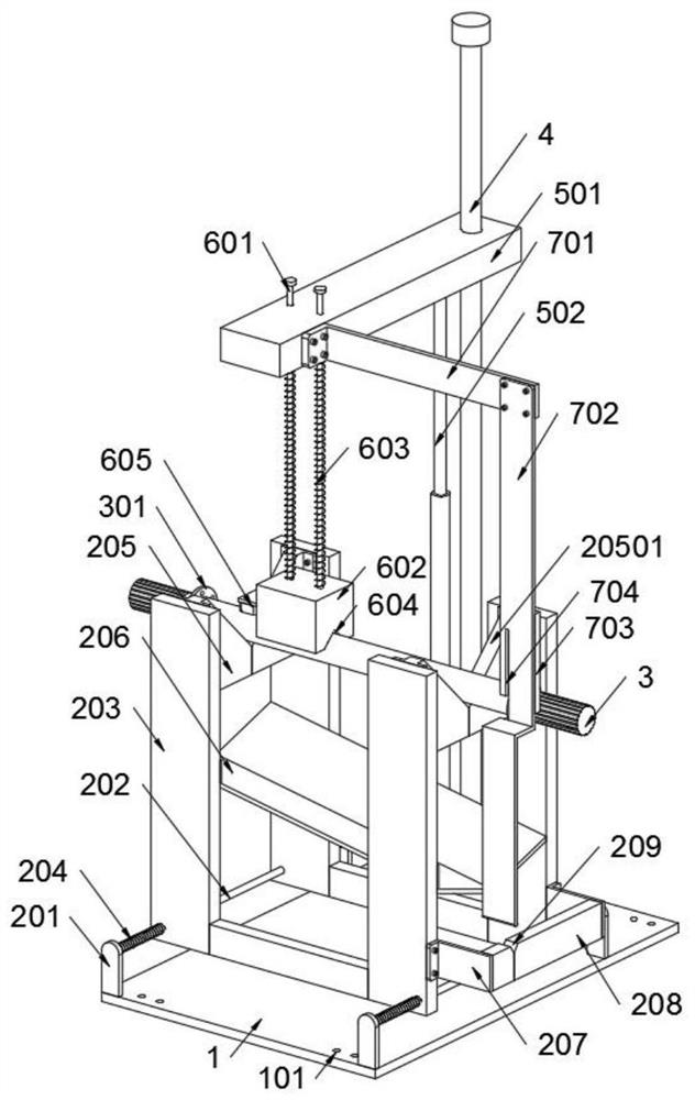
[0007] In order to solve the above-mentioned technical problems, the present invention provides an integrated device for the drive shaft to roll, clean, code, and discharge materials, so as to solve the existing problem that the existing devices often manually rotate the rotating shaft when coding the drive shaft. To realize the circular coding on the outer wall of the transmission shaft, the operation is cumbersome, and the manual adjustment error is relatively large; moreover, after the coding of the transmission shaft is completed, the transmission shaft needs to be moved away, which is labor-intensive and cannot be passed through the structure. Improvement in the coding process to realize the axial rotation of the transmission shaft in linkage, and realize the limit of the transmission while the axial rotation of the transmission shaft, and automatically realize the unloading of the transmission after the coding is completed

Method used


Image

  • Integrated device with transmission shaft having rolling cleaning, coding and discharging functions
  • Integrated device with transmission shaft having rolling cleaning, coding and discharging functions
  • Integrated device with transmission shaft having rolling cleaning, coding and discharging functions

Examples


Embodiment

[0033] as attached figure 1 To attach Figure 8 Shown:

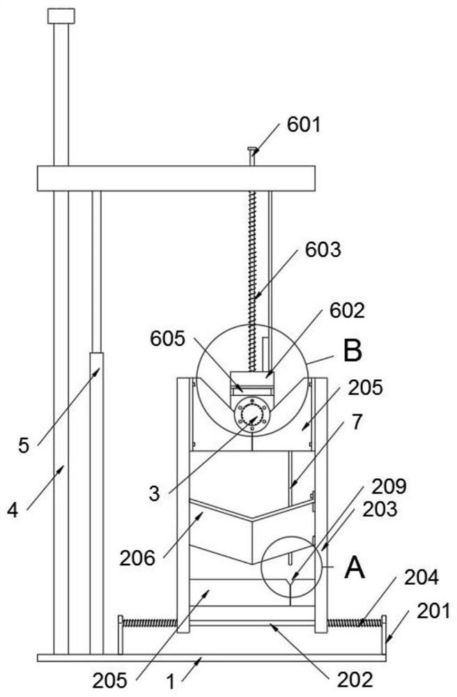
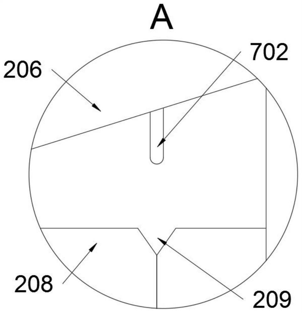
[0034] The present invention provides an integrated device for transmission shafts with rolling, cleaning, coding and unloading, including a base 1; a placement structure 2 is welded on the base 1, and a transmission shaft 3 is placed on the placement structure 2, and a sliding bar B4 is welded on the base 1 ; The sliding bar B4 is slidingly connected with an adjustment structure 5, and the adjustment structure 5 is equipped with a coding structure 6, and the adjustment structure 5 is also equipped with a toggle structure 7; figure 1 The toggling structure 7 includes a connecting plate 701, a toggling arm 702 and a friction block 703, the connecting plate 701 is fixedly connected to the sliding arm 501 by bolts, and a toggling arm 702 is fixedly connected to the connecting plate 701 by bolts; The head end of the arm 702 is an arc-shaped structure, and the head end of the toggle arm 702 is aligned with the V-shaped stre...


PUM


Abstract

The invention provides an integrated device with a transmission shaft having rolling cleaning, coding and discharging functions, and relates to the technical field of coding devices. The problems that axial rotation of the transmission shaft cannot be achieved through linkage in the coding process through structural improvement, transmission limiting cannot be achieved while the transmission shaft rotates axially, and transmission discharging cannot be automatically achieved after coding is completed are solved. The integrated device with the transmission shaft having the rolling cleaning, coding and discharging functions comprises a base. A placement structure is welded to the base, the transmission shaft is placed on the placement structure, and a sliding rod B is welded to the base. Due to the fact that a clamping groove is formed in a stirring arm, the inner wall of the clamping groove is in contact with a flange, and the clamping groove is of a semi-open groove-shaped structure; the width of the clamping groove is equal to that of the flange, the clamping groove forms a limiting structure of the flange and the transmission shaft, and therefore when the transmission shaft is placed on a placement seat, a preset position can be rapidly found; and when the transmission shaft rotates for coding, the transmission shaft can be prevented from moving through the clamping groove.

Description

technical field [0001] The invention belongs to the technical field of coding devices, and more specifically relates to an integrated device with rolling, cleaning, coding and unloading of a transmission shaft. Background technique [0002] The transmission shaft is composed of a shaft tube, a telescopic sleeve and a universal joint. The transmission shaft connects or assembles various accessories, and the movable or rotating circular object accessories are generally made of light and torsion-resistant alloy steel pipes. After the transmission shaft is produced, it needs to be coded. [0003] For example, the application number: CN201920446843.2, discloses a tooling fixture for fast coding of the transmission shaft, including a base, the base surface of the base is fixedly connected with a motor base and a vertical plate, and the base surface of the motor base is fixedly connected with a motor. One end of the motor is axially connected with the first gear, the side wall of ...

Claims


Application Information

Patent Timeline
Patent Type & Authority Applications(China)
IPC IPC(8): B41J3/407B65G47/74B65G47/22
CPCB41J3/4073B65G47/74B65G47/22
Inventor 姚秀兰
Owner 重庆南雁实业集团龙剑机械制造有限公司
Learn More