Electric connector

A technology of electrical connectors and conductive terminals, applied in the field of electrical connectors, can solve the problems of loosening, affecting the electrical contact effect of flexible printed circuit boards, unable to ensure reliable signal transmission, etc., to achieve the effect of ensuring signal transmission.

Inactive Publication Date: 2003-11-26
FOXCONN (KUNSHAN) COMPUTER CONNECTOR CO LTD +1
View PDF4 Cites 0 Cited by
  • Summary
  • Abstract
  • Description
  • Claims
  • Application Information

AI Technical Summary

Problems solved by technology

However, the cover 51 of the electrical connector 5 is clamped and pivoted on the base 50 by its two clamping walls 511 at the same time, so that the clamping arm 512 of the cover 51 is clamped in the recess 502 of the base 50 , the cover body 51 must also be properly moved forward relative to the base 50, which is likely to cause improper relative positions of the two holding walls 511 of the cover body 51 relative to the base 50, resulting in insufficient contact between the flexible printed circuit board 6 and the elastic terminal 52 , so it is obviously impossible to ensure the reliable transmission of signals in between
Furthermore, the cover 51 is positioned on the base 50 only by the clamping arm 512 of the cover 51 and the notch 502 of the base 50 being clamped, and the semicircular cylinder 501 on the rear side is not connected to the alcove. A holding force can be provided in any direction. Therefore, if the manufacturing error of the clamping arm 512 or the notch 502 is too large or wear occurs after a period of use, the cover body may become loose on the base, thereby causing Affect the electrical contact effect between the flexible printed circuit board 6 and the elastic terminal 52

Method used


Image

  • Electric connector
  • Electric connector
  • Electric connector

Examples


Embodiment Construction

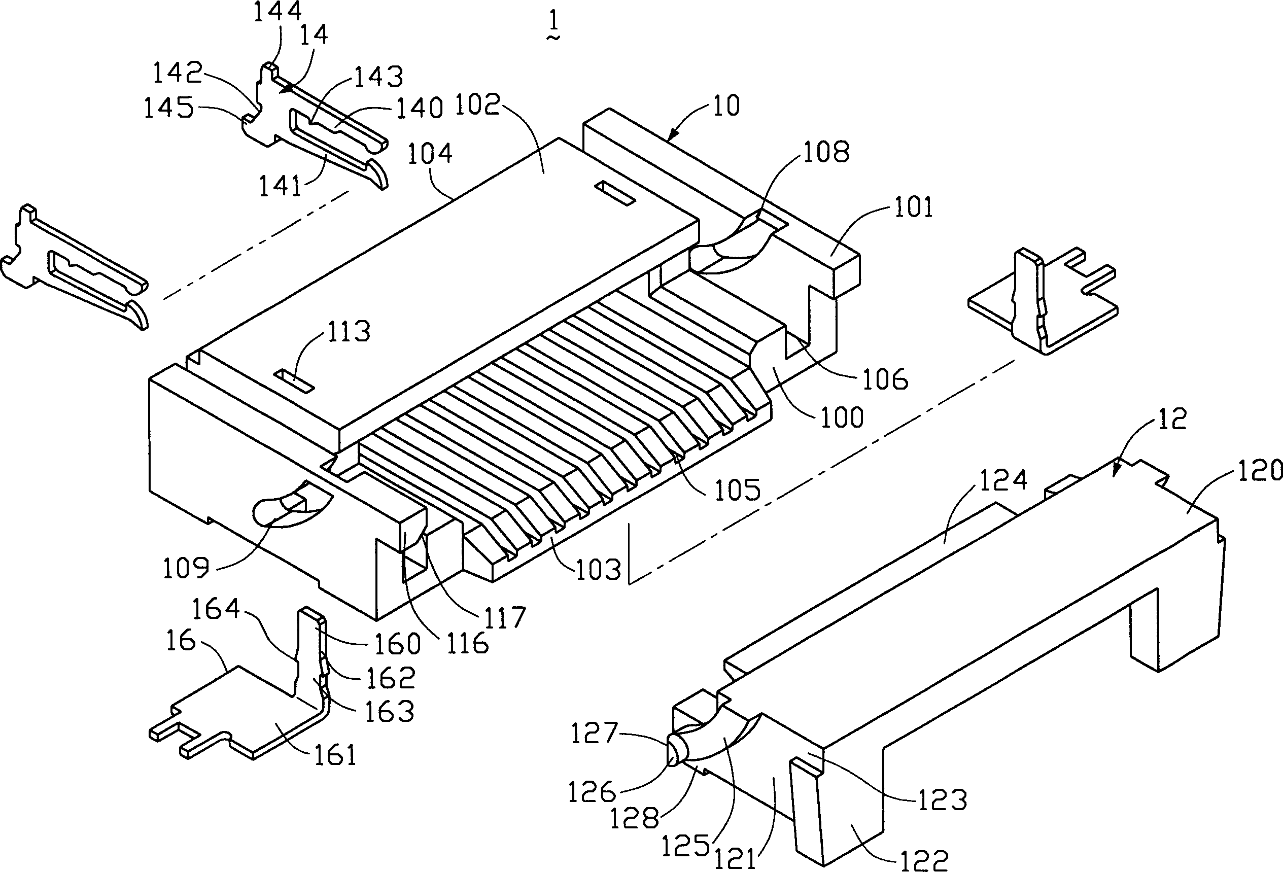
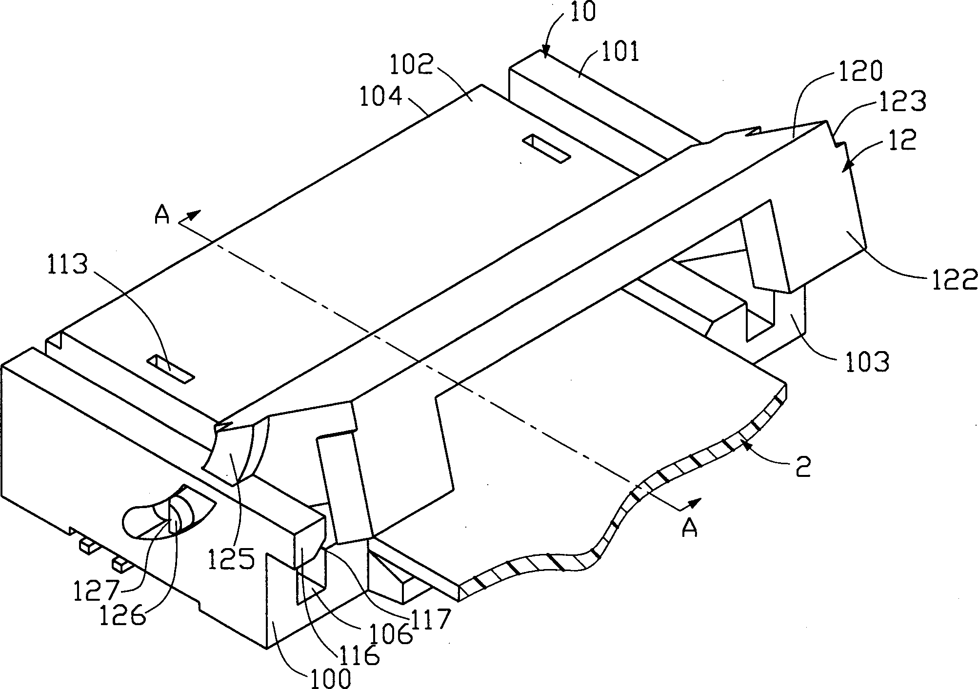
[0013] see figure 2 As shown, the electrical connector 1 of the present invention includes a base 10 , a cover 12 , conductive terminals 14 and a holding member 16 . The base 10 includes a base 100 , side walls 101 vertically disposed on both sides of the base 100 and a top plate 102 opposite to the base 100 . Wherein the base 100 is provided with a plurality of lower terminal receiving grooves 105 penetrating through the docking surface 103 and the connecting surface 104 of the base 10, and the two sides of the base 100 are symmetrically provided through the docking surface 103 and the connecting surface 104 of the base 10 for connecting with the cover 12 The groove 106 is engaged with each other, and an opening 107 ( Figure 7 shown). And the side wall 101 is provided with an arc-shaped inner chute 108 on the side adjacent to the docking surface 103 of the base 10 and connected to the groove 106, and the top of the inner chute 108 communicates with the upper surface of th...


PUM


Abstract

The electric connector includes pedestal, cover and conducting terminals; the pedestal includes base with arced tunned, side wall and top board; and the cover includes top wall and clamping wall having raised strip corresponding to the runner and with reed rhizome at its one end. The cover is assembled to the base via the raised strip with reed rhizome and runner. After flexible printed circuit board is inserted into the connector, some force is applied to the conver to make it rotate around the central axle of circular runner, press the flexible printed circuit board to conducting terminals and connect printed circuit board to the connector electrically.

Description

【Technical field】 [0001] The present invention relates to an electrical connector, in particular to an electrical connector for electrically connecting a Flexible Printed Circuit Board (FPCB) and other electronic devices. 【Background technique】 [0002] For prior art related to the present invention, refer to US Patent Nos. 4,778,403, 5,458,506, 5,580,272, 5,904,586 and other cases. see figure 1 Shown is a working diagram of the existing electrical connector, the existing electrical connector 5 includes a base 50 and a cover 51 pivotally connected to the base 50, wherein the base 50 is provided with a number of terminals passing through its front and rear surfaces The receiving groove 500, the elastic terminal 52 is accommodated in the corresponding terminal receiving groove 500, and the front part of the contact part 520 of the elastic terminal 52 is exposed, and a semicircular cylinder 501 is protruded in the middle of the two opposite side walls of the base 50 (shown by...

Claims


Application Information

Patent Timeline
Patent Type & Authority Patents(China)
IPC IPC(8): H01R12/08H01R12/24H01R12/38H01R12/78
Inventor 林奕雁
Owner FOXCONN (KUNSHAN) COMPUTER CONNECTOR CO LTD
Why Eureka
Try Eureka