Wind-resistant high-bearing door and window sliding support hinge

A sliding brace hinge, door and window technology, applied in door/window accessories, pinned hinges, wing fan components, etc., can solve the problems of reducing the bearing capacity of door and window hinges, reducing the stability of connecting rods, and poor wind pressure resistance, etc. Achieve the effect of improving sliding safety, improving wind pressure resistance, and improving load-bearing capacity

Pending Publication Date: 2021-06-08
揭阳市揭东英特兴业五金制品有限公司
View PDF10 Cites 0 Cited by
  • Summary
  • Abstract
  • Description
  • Claims
  • Application Information

AI Technical Summary

Problems solved by technology

[0002] Door and window hinges are often used for auxiliary support connection between doors and windows and window frames to improve the safety of doors and windows when opening and closing. Most of the existing door and window hinges are installed with connecting rods superimposed on a riveting hole. For better fixing, it is necessary to Reduce the thickness of the connecting rod, which will reduce the load-bearing

Method used


Image

  • Wind-resistant high-bearing door and window sliding support hinge
  • Wind-resistant high-bearing door and window sliding support hinge
  • Wind-resistant high-bearing door and window sliding support hinge

Examples


Example Embodiment

[0017] The present invention will be described in detail below with reference to the drawings.

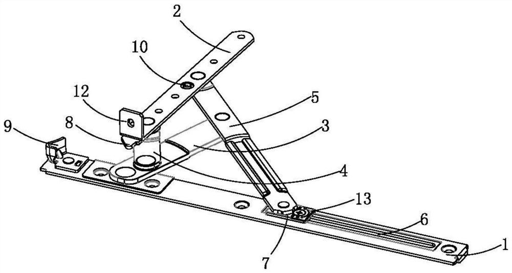
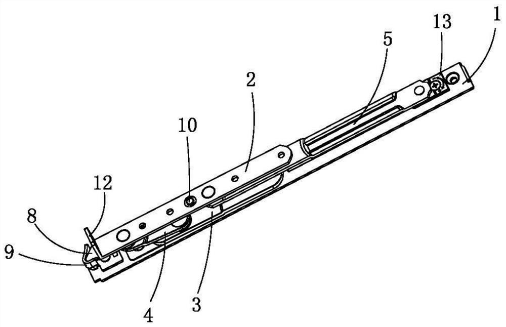
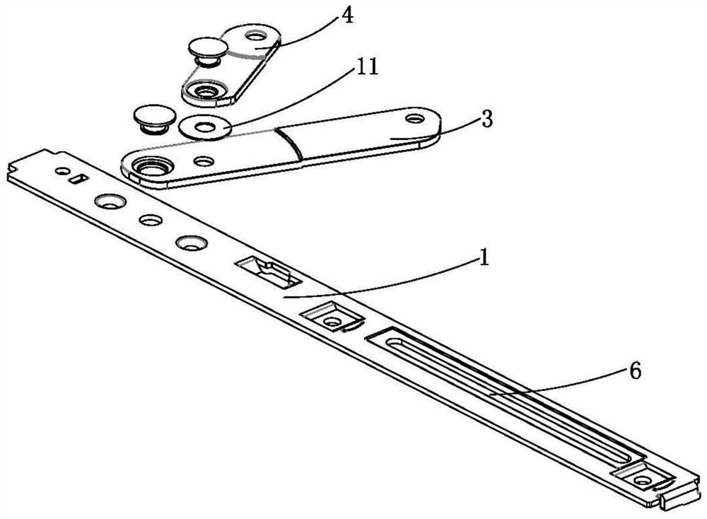
[0018] Such as Figure 1-3 As shown, the wind is strong, the heavy door window sliding hinge, including the hinge body, the hinge body includes a window frame mounting plate 1, a window fan mounting plate 2, a first link 3, a second link 4, and a third link 5, a window frame The mounting plate 1 is provided with a restricted chute 6, and the limit slide 6 is slidably provided with a limit slider 7, and one end of the first link 3 is riveted with the window frame mounting plate 1, and the other end of the first link 3 and the third The link 5 is riveted, and one end of the second link 4 is riveted with the first link 3, and the other end of the second link 4 is riveted, and one end of the third link 5 is fixed to the limit block. The other end of the triple rod 5 is riveted, and the riveting point between the first link 3, the second link 4, and the third link 5 is different, and the fan...


PUM

PropertyMeasurementUnit
Thicknessaaaaaaaaaa

Abstract

The invention relates to the technical field of door and window hinges, and particularly relates to a wind-resistant high-bearing door and window sliding support hinge. The wind-resistant high-bearing door and window sliding support hinge comprises a window frame mounting plate, a window sash mounting plate, a first connecting rod, a second connecting rod and a third connecting rod, wherein the window frame mounting plate is provided with a limiting sliding groove, a limiting sliding block is arranged in the limiting sliding groove in a sliding mode, the first connecting rod is riveted to the window frame mounting plate and the third connecting rod, the second connecting rod is riveted to the first connecting rod and the window sash mounting plate, the third connecting rod is fixedly connected with a limiting block and riveted to the window sash mounting plate, the window sash mounting plate is provided with a limiting nail, the limiting nail is arranged at the lower end of the riveting position of the third connecting rod and the window sash mounting plate, the limiting sliding block is provided with an adjusting screw, and the sliding speed of the limiting sliding block in the limiting sliding groove is set. The second connecting rod is connected with the first connecting rod and the window sash mounting plate, the longitudinal stress area is increased, the bearing capacity is effectively improved, the anti-deformation capacity is improved, the maximum opening angle of the sliding support hinge is limited, the wind pressure resistance of the sliding support hinge is improved, and the safety is improved.

Description

technical field [0001] The invention relates to the technical field of door and window hinges, in particular to a wind-resistant and load-bearing sliding stay hinge for doors and windows. Background technique [0002] Door and window hinges are often used for auxiliary support connection between doors and windows and window frames to improve the safety of doors and windows when opening and closing. Most of the existing door and window hinges are installed with connecting rods superimposed on a riveting hole. For better fixing, it is necessary to Reduce the thickness of the connecting rod, which will reduce the load-bearing capacity of the door and window hinges. If the corresponding thickness of the connecting rod is maintained for the load-bearing capacity, the stability of the connecting rod will be reduced. The connecting rods are hinged with each other to form a hinge. Due to the lack of stoppers, the wind pressure resistance is relatively poor, and the window is likely ...

Claims


Application Information

Patent Timeline
IPC IPC(8): E05D3/18E05D5/00E05D11/10
CPCE05D3/18E05D5/00E05D11/1028E05Y2900/148
Inventor 高俊涛林征良
Owner 揭阳市揭东英特兴业五金制品有限公司
Why Eureka
Try Eureka