
Method and device for setting electromagnetic environment monitoring points of transformer substation

A technology for environmental monitoring and substations, applied in the direction of electromagnetic field characteristics, etc., can solve the problems of large differences in monitoring values, large randomness and subjectivity, and can not reflect the electromagnetic environment of substations well, and achieve the effect of accurate setting.

Active Publication Date: 2021-06-08
JIANGSU FRONTIER ELECTRIC TECH +1
View PDF7 Cites 0 Cited by
  • Summary
  • Abstract
  • Description
  • Claims
  • Application Information

AI Technical Summary

Problems solved by technology

[0003] At present, the method in actual operation is usually to select a monitoring position outside the side of each side of the four side walls of the substation, or to monitor on the side of the wall near the sensitive point, but the selection of the monitoring position is carried out by personnel on site by using portable instruments. Testing, at the same time, according to the on-site analysis of the personnel on the substation to determine the monitoring position, the randomness and subjectivity are relatively large, even outside the wall on the same side, there are many positions that can be selected, and the positions selected by different personnel will vary greatly. Further, the monitoring values ​​are quite different, and the selected location cannot reflect the electromagnetic environment of the substation very well.

Method used


Image

  • Method and device for setting electromagnetic environment monitoring points of transformer substation
  • Method and device for setting electromagnetic environment monitoring points of transformer substation
  • Method and device for setting electromagnetic environment monitoring points of transformer substation

Examples


Embodiment Construction

[0059] In order to make the purpose, technical solutions and advantages of the embodiments of the present application clearer, the technical solutions in the embodiments of the present application will be clearly and completely described below in conjunction with the drawings in the embodiments of the present application. Obviously, the described embodiments are only It is a part of the embodiments of this application, not all of them. The components of the embodiments of the application generally described and illustrated in the figures herein may be arranged and designed in a variety of different configurations. Accordingly, the following detailed description of the embodiments of the application provided in the accompanying drawings is not intended to limit the scope of the claimed application, but merely represents selected embodiments of the application. Based on the embodiments of the present application, every other embodiment obtained by those skilled in the art withou...


PUM


Abstract

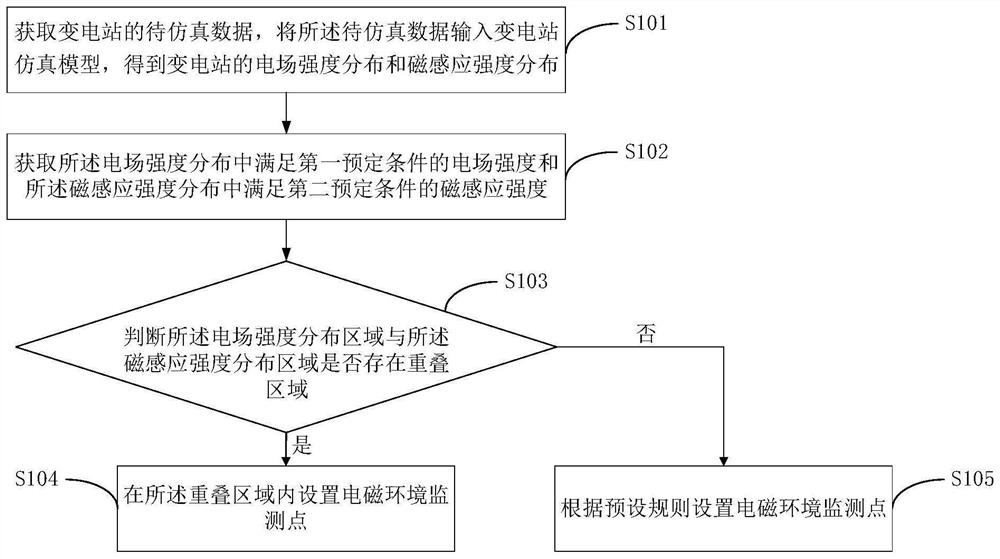
The invention provides a method and device for setting electromagnetic environment monitoring points of a transformer substation, and the method comprises the steps of obtaining the to-be-simulated data of the transformer substation, inputting the to-be-simulated data into a transformer substation simulation model, and obtaining the electric field intensity distribution and the magnetic induction intensity distribution of the transformer substation; acquiring the electric field intensity meeting a first preset condition in the electric field intensity distribution and the magnetic induction intensity meeting a second preset condition in the magnetic induction intensity distribution; judging whether an overlapping region exists between a distribution region of the electric field intensity meeting the first preset condition in the electric field intensity distribution and a distribution region of the magnetic induction intensity meeting the second preset condition in the magnetic induction intensity distribution or not to obtain a judgment result; and setting the electromagnetic environment monitoring points according to the judgment result. According to the method and the device, the electromagnetic environment monitoring points of the transformer substation can be set more scientifically and accurately.

Description

technical field [0001] The present application relates to the technical field of substation electromagnetic environment monitoring, in particular to a method and device for setting up substation electromagnetic environment monitoring points. Background technique [0002] The electromagnetic environment of the substation is an important environmental pollution emission factor of the substation. In recent years, with the development of economy and society, many cities have carried out the expansion and reconstruction of power supply network, and now many substations are already located in the central area of ​​the city. Some members of the public are "disgusted" about the electromagnetic induction of substations, thinking that the radiation generated by substations will endanger the public's health, and complained that the radiation of substations exceeds the standard. Therefore, it is necessary to monitor the power frequency electromagnetic environment of the substation and ...

Claims


Application Information

Patent Timeline
Patent Type & Authority Applications(China)
IPC IPC(8): G01R29/08
CPCG01R29/08Y02E60/00
Inventor 黄轶康杨晓梅祁建民曹文勤傅高健邱勇军黄治军李国奇石田
Owner JIANGSU FRONTIER ELECTRIC TECH
Learn More