
Block chain data storage system

A data storage system and blockchain technology, applied in the blockchain field, can solve the problems of the connection frame being difficult to accommodate the main body of protection, damage, and speeding up the rotation speed.

Inactive Publication Date: 2021-06-08
谢美玲
View PDF0 Cites 0 Cited by
  • Summary
  • Abstract
  • Description
  • Claims
  • Application Information

AI Technical Summary

Problems solved by technology

[0003] Generally, the blockchain data storage system and the whole string of keychains are carried on the keychain. During this process, the main body will be stored inside the connection frame. However, since the edges of the key are rounded and protruding, the It will squeeze in from both sides of the connection frame to push the main body to turn outward from the connection frame, so that the main body will accelerate the rotation speed with the direction of the key, causing the main body to be damaged by the key insertion, making the connection frame difficult. Achieve the role of storing and protecting the main body, reducing the security of the system

Method used


Image

  • Block chain data storage system
  • Block chain data storage system
  • Block chain data storage system

Examples


Embodiment 1

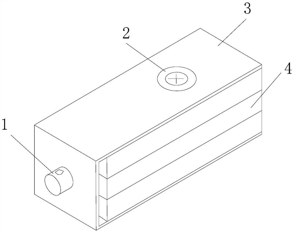
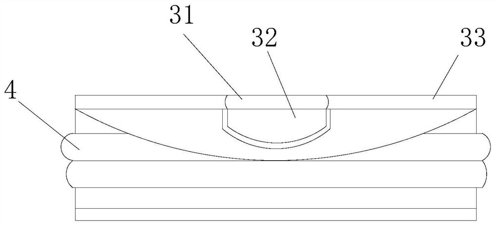
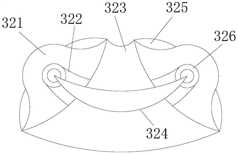
[0027] Such as Figure 1-Figure 3 As shown, the present invention provides a blockchain data storage system, the structure of which includes a buckle head 1, a rotating shaft 2, a connection frame 3, and a system main body 4, the buckle head 1 is fixedly connected to the connection surface of the connection frame 3, and the connection The frame 3 is indirectly matched with the system main body 4 through the rotating shaft 2. The connecting frame 3 includes a one-way page 31, a booster mechanism 32, and a frame 33. The one-way page 31 is welded to the frame 33, and the frame 33 is 32 is indirectly matched with both sides of the system main body 4. The booster mechanism 32 includes a stress plate 321, a running-in belt 322, a dive groove 323, a rebound device 324, a blocking structure 325, and a chain 326. The stress plate 321 is obliquely socketed and connected to the On both sides of the ditch 323, and the bottom of which is equipped with a blocking structure 325, the connecti...

Embodiment 2

[0029] Such as Figure 4-Figure 7 As shown, on the basis of Embodiment 1, the present invention combines the mutual cooperation of the following structural components. The rebound device 324 includes a docking cavity 4a1, a telescopic belt 4a2, a spacer belt 4a3, and a plug-in 4a4. Both sides of the docking cavity 4a1 are fixed There are two telescopic belts 4a2 connected, which are respectively welded and connected to the two sides of the spacer belt 4a3. The spacer belt 4a3 is transitionally fitted with the insert 4a4, and its two ends pass through the groove of the connecting ring 326 and the subduction groove 323. The plug-in 4a4 includes a positioning piece a41, a top cover a42, a guard plate a43, a card position support a44, and a spiky ball a45, and the top cover a42 and the guard plate a43 are socketed and connected between the positioning pieces a41 , and the tip of the clamping support a44 is embedded and connected with the telescopic belt 4a2. The clamping support a...


PUM


Abstract

The invention discloses a block chain data storage system which structurally comprises a buckle head, a rotating shaft, a connecting frame and a system main body. The buckle head is connected to the connecting face of the connecting frame, the connecting frame is indirectly matched with the system main body through the rotating shaft, the connecting frame comprises a one-way page, a power assisting mechanism and a frame, the one-way page is connected to the frame, the frame is indirectly matched with the two sides of the system main body through the power-assisted mechanism, a rebound device and blocking structures are arranged in the power-assisted mechanism, and the rebound device and the blocking structures are matched with a diving groove, so that when a key is squeezed from the two sides of the connecting frame, the key slides along the groove-shaped structure of the diving groove firstly, the rebounding device is pressed to be matched with the blocking structures on the two sides to limit the trend of the key, the channel size of the diving groove is driven to be changed, the key is continuously extruded outwards, the effect efficiency of assisting the system main body to rotate out when the key is opened is achieved, and external objects can be prevented from making contact with and pushing the system main body when the key is closed.

Description

technical field [0001] The present invention relates to the field of block chain, in particular, it is a block chain data storage system. Background technique [0002] In modern technology, there are many devices that need to store data in real time. Real-time data is often stored in a storage medium, such as SD card, U disk, mobile hard disk, etc. Among them, mobile hard disk is widely used because of its large data storage capacity. Existing The blockchain data storage system is prone to the following disadvantages: [0003] Generally, the blockchain data storage system and the whole string of keychains are carried on the keychain. During this process, the main body will be stored inside the connection frame. However, since the edges of the key are rounded and protruding, the It will squeeze in from both sides of the connection frame to push the main body to turn outward from the connection frame, so that the main body will accelerate the rotation speed with the direction...

Claims


Application Information

Patent Timeline
Patent Type & Authority Applications(China)
IPC IPC(8): G06K19/077G11B33/02G11B33/14
CPCG06K19/07732G11B33/025G11B33/14
Inventor 张秀月
Owner 谢美玲
Learn More