
Anti-condensation electric power outdoor cabinet

A technology for power users and anti-condensation, which is applied in the substation/distribution device casing, electrical components, substation/switch layout details, etc. Operation, large area and other problems

Active Publication Date: 2021-06-08
STATE GRID ZHEJIANG ELECTRIC POWER CO LTD JINHUA POWER SUPPLY CO
View PDF5 Cites 0 Cited by
  • Summary
  • Abstract
  • Description
  • Claims
  • Application Information

AI Technical Summary

Problems solved by technology

People's life without electricity will become a mess, and most of the activities that we take for granted in daily life will become very difficult. When there is a problem with the power supply, the urban water supply system will also collapse. The normal operation and development of a city is inseparable from electricity. , so ensuring the safety of power supply has become an important part of ensuring national strategic energy security. The use of switch cabinets is increasing, and the heat generated by electrical components is also gradually increasing. Due to the temperature rise of the main body of the equipment and the large-scale changes in the external environment, surface condensation has become a major risk problem for high-voltage circuits. Therefore, it is necessary to send air to the cabinet to achieve temperature rise or cool down to dehumidify to ensure the normal operation of electrical equipment. The existing anti-condensation temperature control device is assembled according to the needs of the site. Due to the different installation environments, the anti-condensation temperature control The on-site installation of the device is messy and occupies a large area, which may easily affect the operation of the anti-condensation temperature control device

Method used


Image

  • Anti-condensation electric power outdoor cabinet
  • Anti-condensation electric power outdoor cabinet
  • Anti-condensation electric power outdoor cabinet

Examples


Embodiment Construction

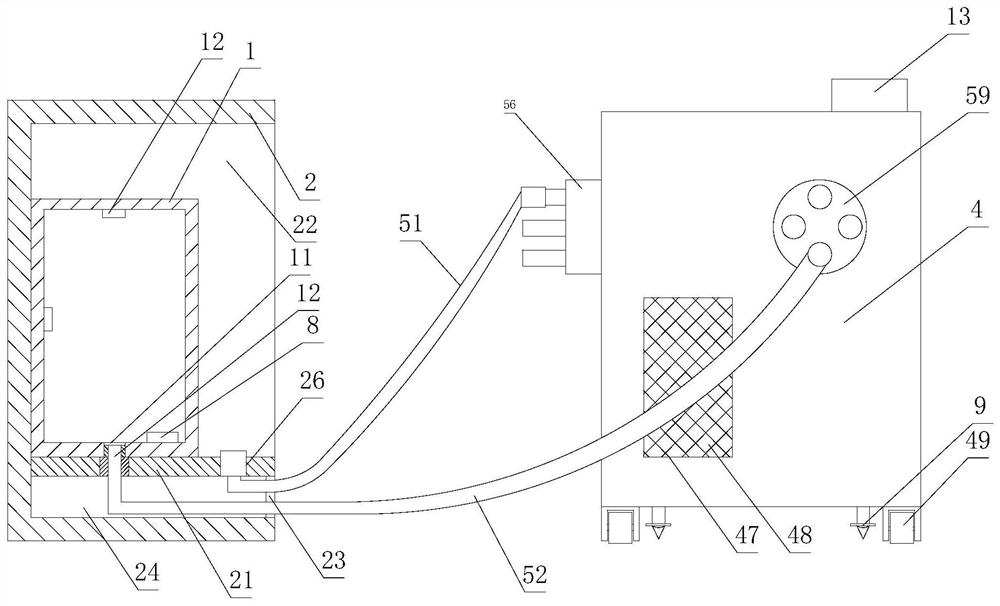
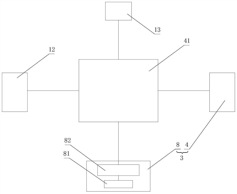
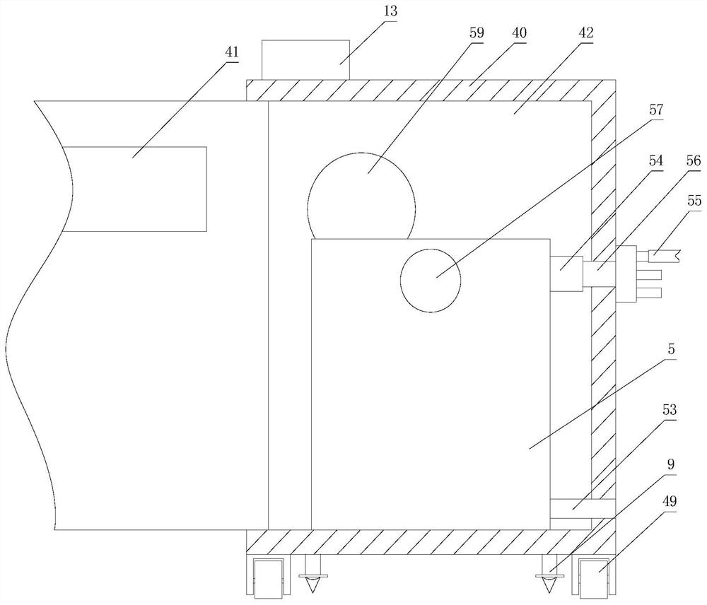
[0027] like figure 1 , figure 2 , image 3 , Figure 4 , Figure 5 , Image 6 , Figure 7 , Figure 8 , Figure 9 As shown, an anti-condensation electric outdoor cabinet includes a cabinet body 1, an outer box body 2 and a temperature control device 3, the temperature control device 3 includes a refrigeration assembly 4 and a heating assembly 8, and the refrigeration assembly 4 includes a mobile cabinet 40 And be arranged on the air conditioner 5 in the mobile cabinet 40, described air conditioner 5 is connected with air inlet pipe 51, air supply pipe 52 and drain pipe 53, described mobile cabinet 40 is provided with the controller 41 that links to each other with air conditioner 5, this The controller 41 in the embodiment adopts a PLC controller, has a structure that is not described in detail in the embodiment, and the mobile cabinet 40 includes a cabinet door, the controller 41 is installed on the cabinet door, and the cabinet body 1 is provided with The temperatur...


PUM


Abstract

The invention relates to an anti-condensation electric outdoor cabinet, which comprises a cabinet body, an outer box body and a temperature control device, the temperature control device comprises a refrigeration assembly and a heating assembly, the refrigeration assembly comprises a mobile cabinet and an air conditioner, the air conditioner is connected with an air inlet pipeline, an air supply pipeline and a drainage pipe, the mobile cabinet is also provided with a controller, and a temperature and humidity sensor is arranged in the cabinet body; the anti-condensation electric outdoor cabinet has the advantages that the temperature and humidity in the cabinet body are collected in real time through the temperature and humidity sensor, and when the temperature and humidity in the cabinet body exceed or reach preset numerical values, the controller can control the refrigeration assembly or the heating assembly in time to control the temperature and humidity in the cabinet body, so that the temperature and humidity in the cabinet body meet the operation requirements of electrical equipment; and therefore, the risk of condensation in the cabinet is eliminated.

Description

technical field [0001] The invention relates to an anti-condensation electric outdoor cabinet. Background technique [0002] Electricity is playing an increasingly important role in today's human society in the 21st century. Not only is production and scientific research inseparable from electricity, but the basic life of the people in the vast urban and rural areas is also inseparable from electricity. People's life without electricity will become a mess, and most of the activities that we take for granted in daily life will become very difficult. When there is a problem with the power supply, the urban water supply system will also collapse. The normal operation and development of a city is inseparable from electricity. , so ensuring the safety of power supply has become an important part of ensuring national strategic energy security. The use of switch cabinets is increasing, and the heat generated by electrical components is also gradually increasing. Due to the tempera...

Claims


Application Information

Patent Timeline
IPC IPC(8): H02B1/56H02B1/30H02B1/52H02B1/50H02B1/28
CPCH02B1/565H02B1/30H02B1/52H02B1/505H02B1/28
Inventor 楼鑫刘建生王旭杰张跃凯郎伟强徐志军陈震陈佳璐朱彦星孟子辰陈思艺毛晋凯
Owner STATE GRID ZHEJIANG ELECTRIC POWER CO LTD JINHUA POWER SUPPLY CO
Learn More