Power grid fault maintenance equipment
A technology for power grid faults and equipment, applied in the field of power grids, can solve the problems of incomplete detection of the internal structure of cables and incomplete bonding of probes, etc.
- Summary
- Abstract
- Description
- Claims
- Application Information
AI Technical Summary
Problems solved by technology
Method used
Image

Examples
Embodiment 1
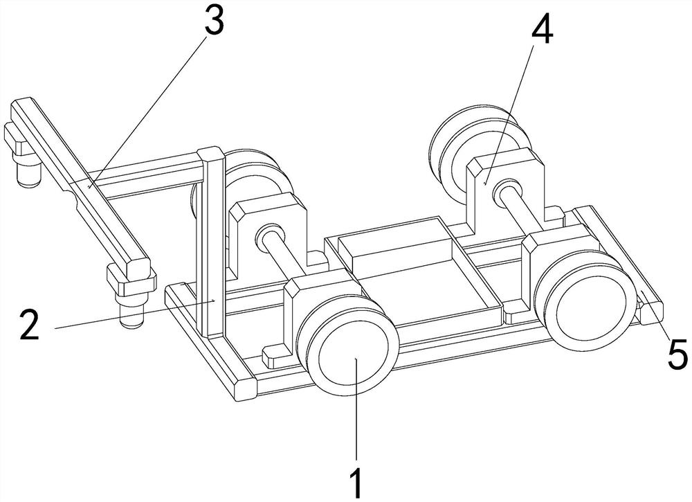
[0025] as attached figure 1 to attach Figure 5 As shown, the present invention provides a power grid fault maintenance equipment, the structure of which includes a movable wheel 1, a vertical rod 2, a detection device 3, a fixed seat 4, and a bottom plate 5. The inner wall on the left side of the movable wheel 1 is connected to the The two ends of the fixing base 4, the lower end of the vertical pole 2 is welded and fixed on the front end above the base plate 5, the rear end of the detection device 3 is movably engaged with the front end of the vertical pole 2, and the lower end of the fixing base 4 is fixed on the upper end of the base plate 5 by screws;
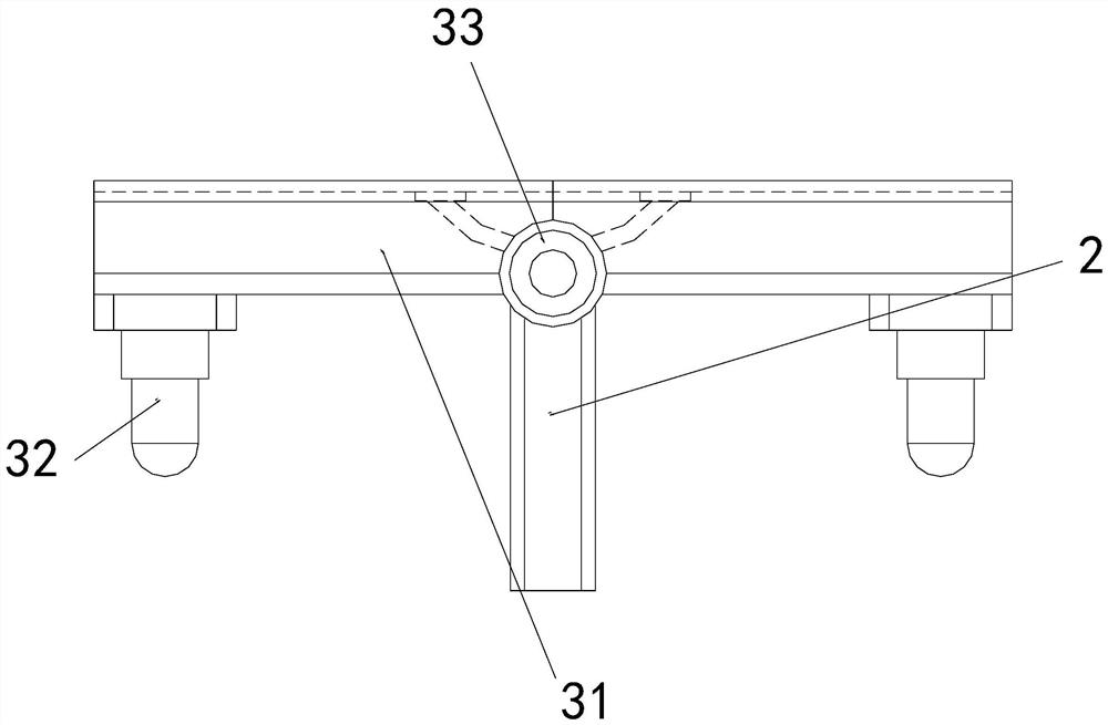
[0026] The detection device 3 is composed of a crossbar 31, a detector 32, and a hinge mechanism 33. The rear end of the crossbar 31 is movably engaged with the front end of the vertical pole 2. Below the two ends of the bar 31, the outer wall of the hinge mechanism 33 is nested and engaged between the cross bars 31. Ther...
Embodiment 2
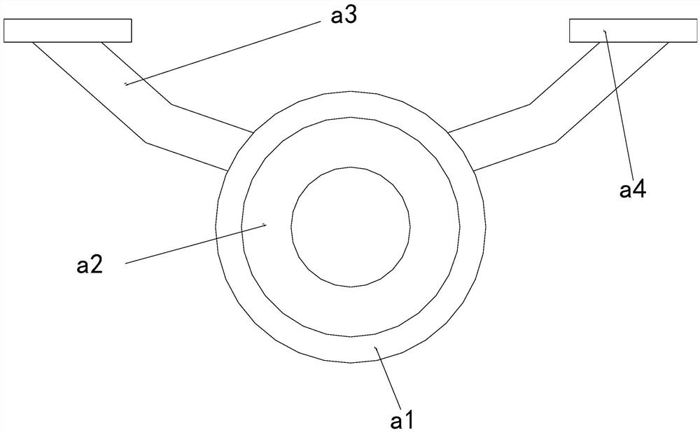
[0032] as attached Image 6 to attach Figure 7 As shown: the detector 32 is composed of a connecting shaft d1, an embedded connecting plate d2, and a detector d3. The outer wall of the upper end of the connecting sleeve d1 is fixed to the lower end of the embedded connecting plate d2 by screws, and the upper end of the detector d3 is movable. Fitted to the lower end of the connecting sleeve shaft d1, the upper end of the embedded connecting plate d2 is connected to the lower ends of the cross bar 31 through buckling.
[0033] Wherein, the inside of the detector d3 is equipped with a detection needle e1, a lifting rod e2, a magnetic ring e3, a piston ring plate e4, and a hollow groove e5. The outer wall of the upper end of the rod e2 is interference-fitted with the inner wall of the magnetic ring e3, the inner wall of the piston ring plate e4 is nested and engaged with the outer wall of the middle section of the elevating rod e2, and the inner wall of the empty groove e5 is i...
PUM
 Abstract
Description
Claims
Application Information
 - R&D
- Intellectual Property
- Life Sciences
- Materials
- Tech Scout
- Unparalleled Data Quality
- Higher Quality Content
- 60% Fewer Hallucinations
Browse by: Latest US Patents, China's latest patents, Technical Efficacy Thesaurus, Application Domain, Technology Topic, Popular Technical Reports.
© 2025 PatSnap. All rights reserved.Legal|Privacy policy|Modern Slavery Act Transparency Statement|Sitemap|About US| Contact US: help@patsnap.com