Supercharge Your Innovation With Domain-Expert AI Agents!

A power grid troubleshooting equipment

A power grid fault and equipment technology, applied in the power grid field, can solve the problems of incomplete detection of the internal structure of the cable and the inability of the probe to fit completely

Active Publication Date: 2022-07-22
山东电工运检工程有限公司
View PDF6 Cites 0 Cited by
  • Summary
  • Abstract
  • Description
  • Claims
  • Application Information

AI Technical Summary

Problems solved by technology

[0003] Aiming at the deficiencies of the prior art, the present invention provides a power grid fault repairing device, which solves the problem that the existing fault repairing devices usually place the device on the upper end of the cable and touch the cable through a probe to detect the internal wires of the cable. However, because the cable is tensioned and assembled between two electric towers, due to the gravity of the cable's own material, the middle section of the cable will sink because it is not supported, causing the cable to appear radians. The problem that the probe of the detection equipment cannot be completely attached to the surface of the cable, and the probe cannot fully detect the internal structure of the cable

Method used


Image

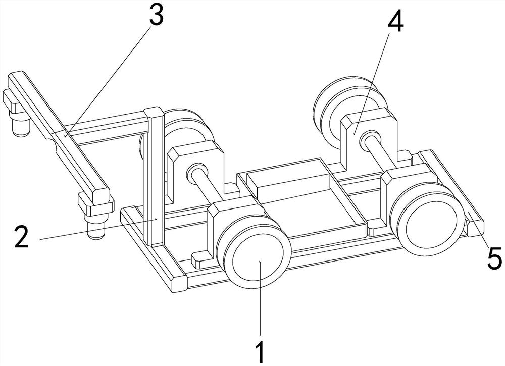
  • A power grid troubleshooting equipment
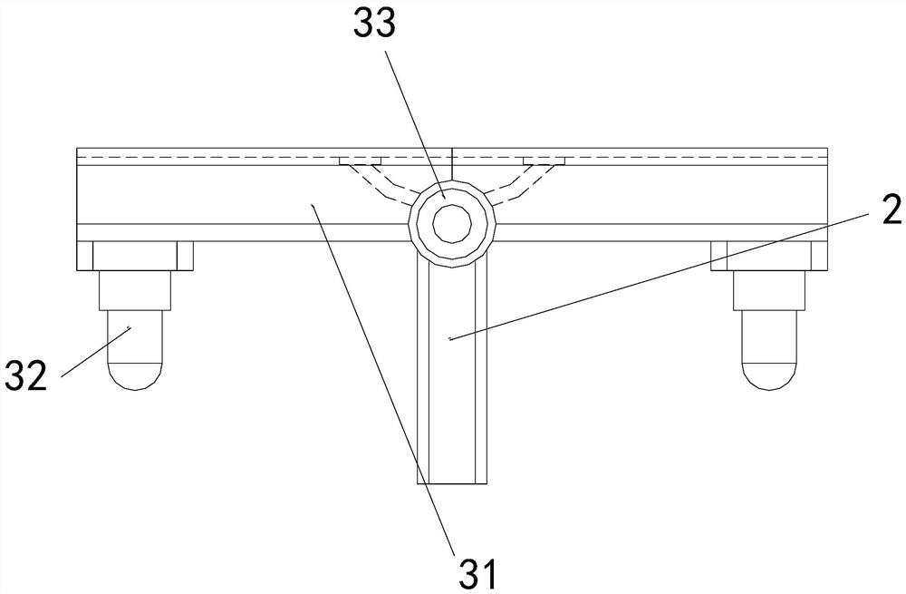
  • A power grid troubleshooting equipment
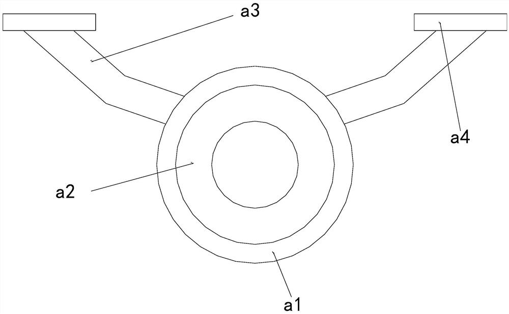
  • A power grid troubleshooting equipment

Examples


Embodiment 1

[0025] as attached figure 1 to the attached Figure 5 As shown in the figure, the present invention provides a power grid fault maintenance equipment, the structure of which includes a movable wheel 1, a vertical rod 2, a detection device 3, a fixed seat 4, and a bottom plate 5, and the left inner wall of the movable wheel 1 is connected by a connecting rod. At both ends of the fixed seat 4, the lower end of the vertical rod 2 is welded and fixed to the upper front end of the bottom plate 5, the rear end of the detection device 3 is movably engaged with the front end of the vertical rod 2, and the lower end of the fixed seat 4 is fixed to the upper end of the bottom plate 5 by screws;

[0026] The detection device 3 is composed of a cross bar 31, a detector 32, and a hinge mechanism 33. The rear end of the cross bar 31 is movably engaged with the front end of the vertical bar 2, and the upper end of the detector 32 is connected to the horizontal bar through snap engagement. B...

Embodiment 2

[0032] as attached Image 6 to the attached Figure 7 As shown: the detector 32 is composed of a sleeve shaft d1, an embedded connecting plate d2, and a detector d3. The upper end outer wall of the sleeve shaft d1 is fixed to the lower end of the embedded connecting plate d2 by screws, and the upper end of the detector d3 is movable. Coupling with the lower end of the connecting sleeve shaft d1, the upper end of the embedded connecting plate d2 is connected to the lower part of the two ends of the cross bar 31 through snap-fit.

[0033] The detector d3 is provided with a probe needle e1, a lift rod e2, a magnetic ring e3, a piston ring plate e4, and an empty groove e5. The inner wall of the upper end of the probe needle e1 is embedded and fixed on the lower end of the lift rod e2. The outer wall of the upper end of the rod e2 is interference-fitted with the inner wall of the magnetic ring e3, the inner wall of the piston ring plate e4 is nested and engaged with the outer wall...


PUM


Abstract

The invention provides a power grid fault maintenance equipment, the structure of which includes a movable wheel, a vertical pole, a detection device, a fixed seat, and a bottom plate. When the power grid is detected, the movable wheel is assembled and clamped to the upper end of the cable, and the detector provided by the detection device is attached to the surface of the cable. When flowing, the cable will have a partial electromagnetic force, and the magnetic force will attract the magnetic ring, so that the probe needle is completely attached to the surface of the cable, and when the device moves to the middle of the cable's stroke, the radian of the cable changes. It also pulls the detector to change the height according to the radian of the cable, and attaches to the surface of the cable through the hinge mechanism to avoid the situation that the radian of the cable causes the equipment to fail to attach the cable and detect the structural state inside the cable.

Description

technical field [0001] The invention relates to the field of power grids, and more particularly, to a power grid fault maintenance device. Background technique [0002] Due to the rapid development and expansion of existing cities, in order to meet the electricity demand of urban residents, part of the land and human resources in the city will be used to build power systems such as power grids, to receive and adjust the power resources transmitted by power stations, and to The adjustment of power resources makes the voltage compound the safe voltage of urban residents' electricity consumption, but due to the gradual increase in urban electricity demand, and the construction of the power grid will also be affected by urban electricity demand and expansion, but due to the amount of urban electricity consumption It is too large and the peak power varies greatly, which has a great impact on the power grid and increases the load of the power grid. In order to ensure the safety of...

Claims


Application Information

Patent Timeline
Patent Type & Authority Patents(China)
IPC IPC(8): H02G1/02G01R31/58
CPCH02G1/02G01R31/58
Inventor 王瑾
Owner 山东电工运检工程有限公司
Features
  • R&D
  • Intellectual Property
  • Life Sciences
  • Materials
  • Tech Scout
  • Unparalleled Data Quality
  • Higher Quality Content
  • 60% Fewer Hallucinations
Learn More