Circuit board test system
A technology for testing systems and circuit boards, applied in the direction of optical testing flaws/defects, measuring devices, instruments, etc., can solve the problems of large space occupation, high missed detection rate, slow detection, etc., achieve high automation efficiency and facilitate rapid detection Effect
- Summary
- Abstract
- Description
- Claims
- Application Information
AI Technical Summary
Problems solved by technology
Method used
Image
Examples
Embodiment 1
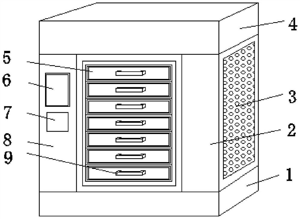
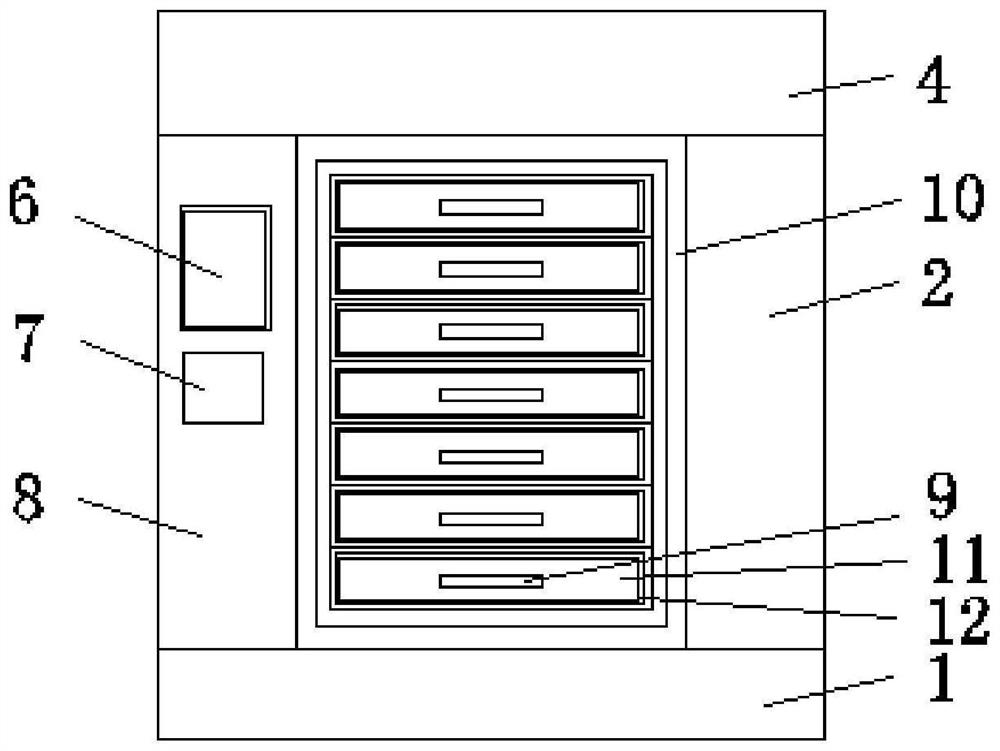
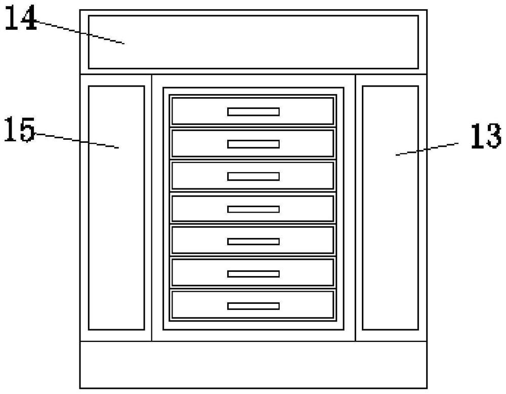
[0032] see Figure 1-7 , in this embodiment: a circuit board testing system, including a test cabinet 1, the upper side of the test cabinet 1 is provided with a right side chassis 2, and one side of the right side chassis 2 is provided with a cooling plate 3, through which heat is conducted through the cooling plate 3, Right side cabinet 2 side is provided with detection cabinet 10, and detection cabinet 10 is provided with left side cabinet 8 far away from the side of right cabinet 2, and one side of left side cabinet 8 is provided with display screen 6, and the lower end of display screen 6 is provided with The operation panel 7 operates the test cabinet 1 through the display screen 6 and the operation panel 7. The test cabinet 10 is provided with a test drawer 11 on the same side as the display screen 6, and the outside of the test drawer 11 is provided with a handle 9. Put in the circuit board to be detected, the top drawer 5 is provided on the top of the test drawer 11, a...
Embodiment 2
[0035] see Figure 1-7, in this embodiment: a circuit board testing system, including a test cabinet 1, the upper side of the test cabinet 1 is provided with a right side chassis 2, and one side of the right side chassis 2 is provided with a cooling plate 3, through which heat is conducted through the cooling plate 3, Right side cabinet 2 side is provided with detection cabinet 10, and detection cabinet 10 is provided with left side cabinet 8 far away from the side of right cabinet 2, and one side of left side cabinet 8 is provided with display screen 6, and the lower end of display screen 6 is provided with The operation panel 7 operates the test cabinet 1 through the display screen 6 and the operation panel 7. The test cabinet 10 is provided with a test drawer 11 on the same side as the display screen 6, and the outside of the test drawer 11 is provided with a handle 9. Put in the circuit board to be detected, the top drawer 5 is provided on the top of the test drawer 11, an...
Embodiment 3
[0038] see Figure 1-7 , in this embodiment: a circuit board testing system, including a test cabinet 1, the upper side of the test cabinet 1 is provided with a right side chassis 2, and one side of the right side chassis 2 is provided with a cooling plate 3, through which heat is conducted through the cooling plate 3, Right side cabinet 2 side is provided with detection cabinet 10, and detection cabinet 10 is provided with left side cabinet 8 far away from the side of right cabinet 2, and one side of left side cabinet 8 is provided with display screen 6, and the lower end of display screen 6 is provided with The operation panel 7 operates the test cabinet 1 through the display screen 6 and the operation panel 7. The test cabinet 10 is provided with a test drawer 11 on the same side as the display screen 6, and the outside of the test drawer 11 is provided with a handle 9. Put in the circuit board to be detected, the top drawer 5 is provided on the top of the test drawer 11, a...
PUM
 Abstract
Description
Claims
Application Information
 - R&D
- Intellectual Property
- Life Sciences
- Materials
- Tech Scout
- Unparalleled Data Quality
- Higher Quality Content
- 60% Fewer Hallucinations
Browse by: Latest US Patents, China's latest patents, Technical Efficacy Thesaurus, Application Domain, Technology Topic, Popular Technical Reports.
© 2025 PatSnap. All rights reserved.Legal|Privacy policy|Modern Slavery Act Transparency Statement|Sitemap|About US| Contact US: help@patsnap.com


