Self-cleaning shake mechanism

A self-cleaning, shaker cup technology, applied to conveyor objects, cleaning methods and utensils, cleaning methods using liquids, etc. The effect of improving work efficiency and reducing the space occupied by equipment

Pending Publication Date: 2021-06-11
XIAMEN YOUXIN INFORMATION TECH CO LTD
View PDF0 Cites 0 Cited by
  • Summary
  • Abstract
  • Description
  • Claims
  • Application Information

AI Technical Summary

Problems solved by technology

[0003] Aiming at the problem that the function and structure of the existing snow gram mechanism is relatively single, which leads to th

Method used


Image

  • Self-cleaning shake mechanism
  • Self-cleaning shake mechanism
  • Self-cleaning shake mechanism

Examples


Example Embodiment

[0024] The existing Snowk institution has a single functional structure, which leads to problems with high labor intensity, high cost and low operating efficiency. Therefore, the present invention proposes a new solution, which will be described in detail below with reference to the accompanying drawings.

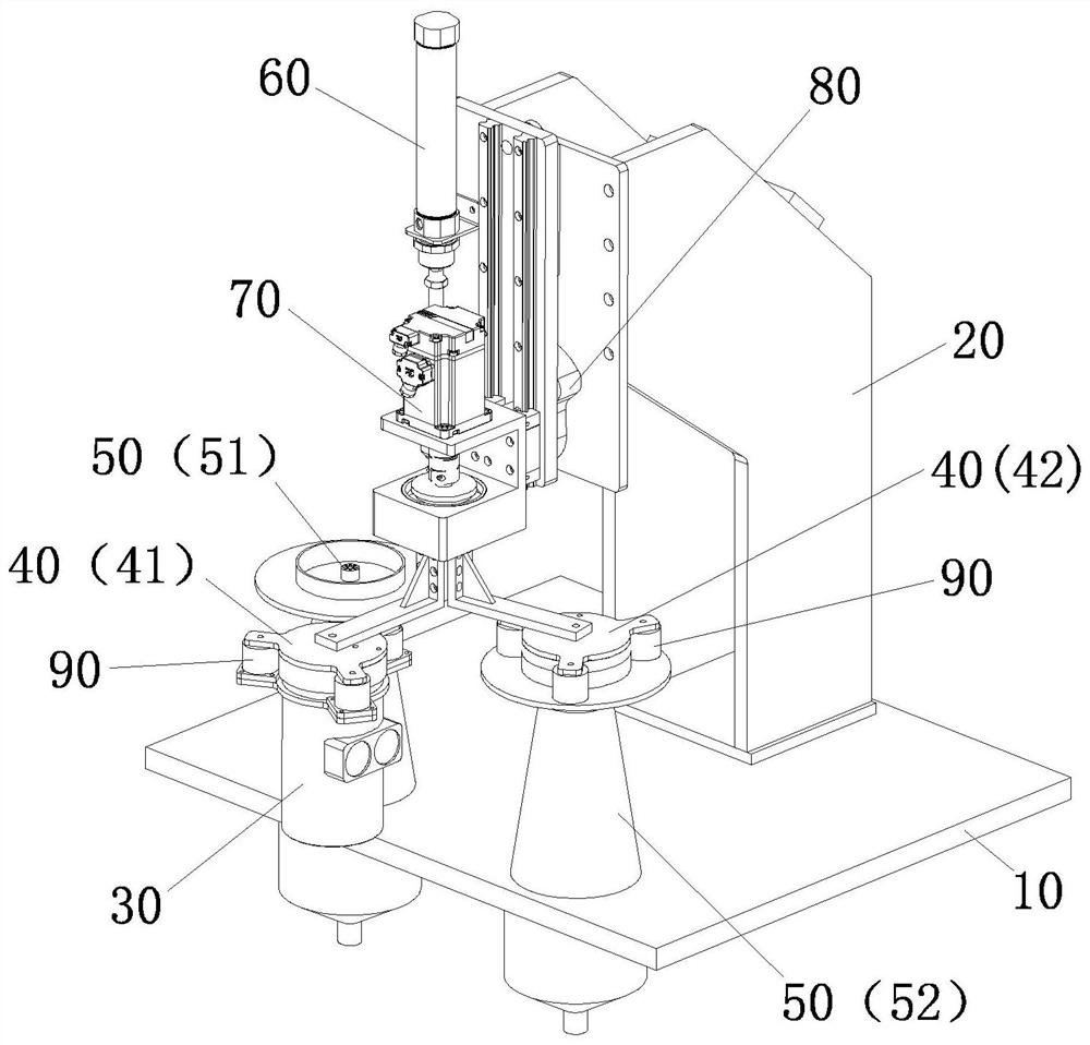
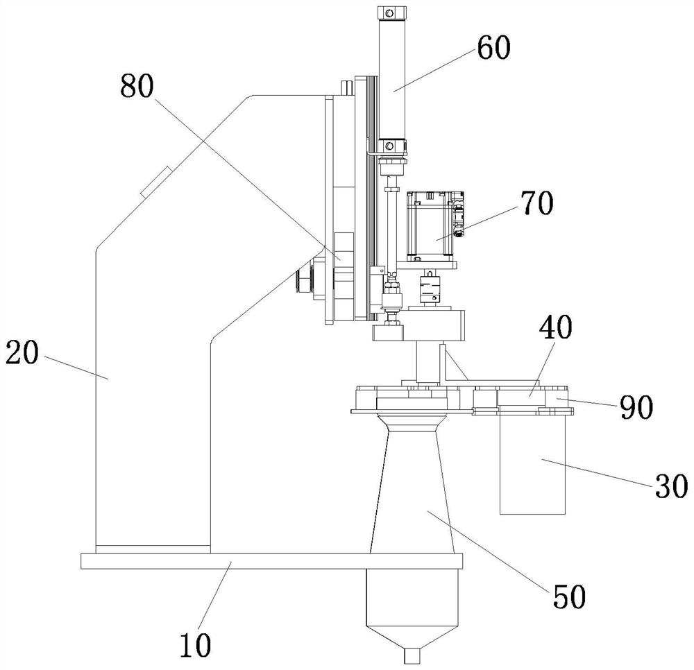
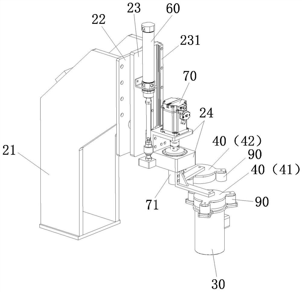
[0025] See Figure 1-5 A Xike mechanism with self-cleaning is disposed on the side of the cycle line (not shown) containing the Syo Cup 30. The Xich mechanism includes a bottom plate 10 and a frame 20 disposed on the bottom plate 10, the frame 20 is provided with a snow-cup cover 40 that mates in conjunction with the Xik Cup 30, and the bottom plate 10 There is a cleaning device 50 for cleaning the chry cup cover 40, and the frame 20 is further provided with a lifting device 60 for moving the Xike Cup 40, for driving the Xik Cup 40 The Xike Cup 30 is moving between the cleaning device 50 and a snowker driving device 80 for performing a snow-moving operation, the Syke Cup 40, whi...


PUM


Abstract

The invention provides a self-cleaning shake mechanism which is arranged on one side of a circulation line carrying shake cup bodies. The self-cleaning shake mechanism comprises a bottom plate and a machine frame arranged on the bottom plate, the machine frame is provided with shake cup covers matched with the shake cup bodies, the bottom plate is provided with a cleaning device used for cleaning the shake cup covers, the machine frame is further provided with a lifting device for driving the shake cup covers to move up and down, a position changing device for driving the shake cup covers to move between the shake cup bodies and the cleaning device, and a shake driving device for performing shake action, and the shake cup covers are provided with adsorption devices fixedly connected with the shake cup bodies or the cleaning device. The self-cleaning shake mechanism integrates shake and cleaning, the occupied space of equipment is effectively reduced, the labor intensity is effectively reduced, and the working efficiency is improved.

Description

technical field [0001] The invention relates to the field of beverage automation equipment, in particular to a self-cleaning shaker mechanism. Background technique [0002] The shaker mechanism is mainly used for the preparation of beverages, and the main steps include putting beverage raw materials into a shaker cup and shaking them through the shaker mechanism. The function of the existing shaker mechanism is relatively single, and only the shaker process is performed, so that the shaker process and the cleaning after the shaker are independent of each other. Therefore, an additional cleaning area needs to be set up, which leads to the problems of occupying space and low work efficiency , and the existing cleaning all adopts a manual method, which has the problems of high labor intensity, high cost and low efficiency. Contents of the invention [0003] Aiming at the problems of relatively single functional structure of the existing shaker mechanism, resulting in high la...

Claims


Application Information

Patent Timeline
IPC IPC(8): B08B3/02B65G47/92
CPCB08B3/02B65G47/92
Inventor 廖锦华陈运连麦彪
Owner XIAMEN YOUXIN INFORMATION TECH CO LTD
Why Eureka
Try Eureka