Supercharge Your Innovation With Domain-Expert AI Agents!

Impurity removing equipment for polypropylene

A polypropylene and equipment technology, applied in the field of polypropylene impurity removal equipment, can solve the problems that the solution cannot be effectively stirred, affect the polypropylene impurity removal effect, etc., and achieve the effect of slowing down the resistance.

Inactive Publication Date: 2021-06-11
陈新云
View PDF0 Cites 0 Cited by
  • Summary
  • Abstract
  • Description
  • Claims
  • Application Information

AI Technical Summary

Problems solved by technology

[0005] In order to solve the above-mentioned technology, because the stirring rod in the impurity removal equipment is embedded at the bottom of the rotating rod, and has a long strip shape, when stirring and removing impurities from polypropylene, only the polypropylene that is at the same level as the stirring rod can be used. The solution is stirred so that the solution at the top cannot be stirred effectively, which in turn affects the effect of the equipment on removing impurities from polypropylene

Method used


Image

  • Impurity removing equipment for polypropylene
  • Impurity removing equipment for polypropylene
  • Impurity removing equipment for polypropylene

Examples


Embodiment 1

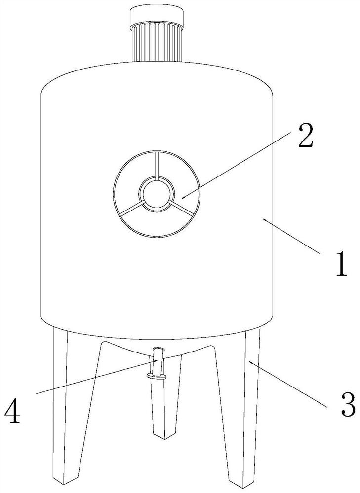
[0025] as attached figure 1 to attach Figure 5 Shown:

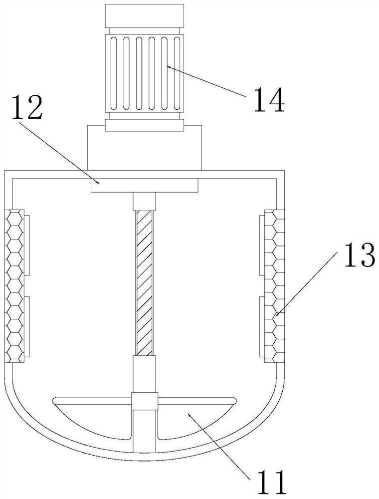
[0026] The invention provides an impurity removal equipment for polypropylene, the structure of which includes an impurity removal tank 1, a valve 2, a bracket 3, and a discharge port 4. The outer end surface of the impurity removal tank 1 is movably fitted with a valve 2, and the valve 2 is located directly above the discharge port 4, the bracket 3 is fixed on the lower end surface of the trash discharge tank 1 by welding, and the discharge port 4 is embedded and installed on the lower end surface of the trash discharge tank 1; the trash discharge tank 1 It includes a stirring mechanism 11, a turntable 12, a heater 13, and a motor 14. The stirring mechanism 11 is embedded and mounted on the lower surface of the turntable 12. The heater 13 is symmetrically installed on the left and right ends of the stirring mechanism 11 , and the motor 14 is embedded directly above the stirring mechanism 11 .

[0027] Wherein, the st...

Embodiment 2

[0033] as attached Figure 6 to attach Figure 7 Shown:

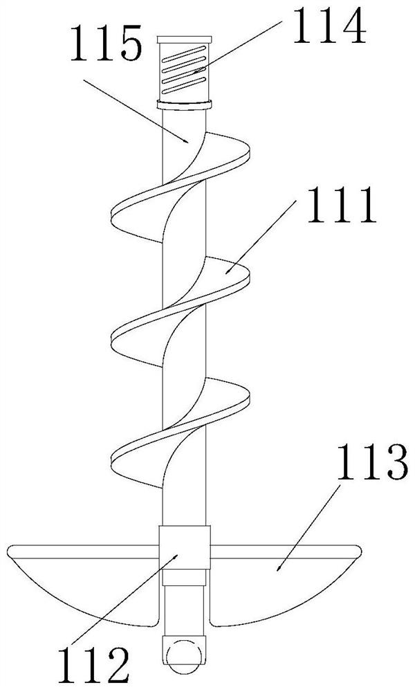
[0034]Wherein, the guide piece 113 includes an arc block 131, a guiding mechanism 132, a limit block 133, a spring 134, and a nesting shaft 135, and the upper end surface on the right side of the arc block 131 is inlaid and engaged with the nesting shaft 135, The guide mechanism 132 is embedded on the inner end surface of the arc block 131, the limiting block 133 is embedded and fixed on the outer end surface of the nested shaft 135, and the spring 134 is fixed on the upper left side of the nested shaft 135 by welding , the nested shaft 135 is inlaid and engaged with the lifting mechanism 112, and the left end surface of the arc block 131 has an arc-shaped outer contour, which can make the stirring mechanism 112 rotate at the same time. solution to guide.

[0035] Wherein, the guide mechanism 132 includes an inclined plane groove 321, a cavity 322, an air bag 323, an arc block 324, and a closing plate 325. On the in...


PUM


Abstract

The invention discloses impurity removing equipment for polypropylene. The impurity removing equipment structurally comprises an impurity discharging tank, a valve, a support and a discharging port, the valve is movably installed on the end face of the outer side of the impurity discharging tank in a clamped mode, the valve is located over the discharging port, the support is fixed to the surface of the lower end of the impurity discharging tank in a welded mode, the discharging port is fixedly installed on the lower end face of the impurity discharging tank in an embedded mode, and a guide groove is in a wavy outline; so that a lifting mechanism is driven by embedding of an embedding bead and a guide groove in the process of rotating along with a rotating rod, a rubber block is extruded to enable a guide sheet to fluctuate up and down, a hot polypropylene solution around a rotating blade can be driven upwards when the rotating blade which is embedded and fixed on the outer side end surface of the rotating rod in a surrounding manner rotates clockwise, and a stirring mechanism is prevented from only stirring the solution around the lower end of the inner side of the impurity discharging tank.

Description

technical field [0001] The invention belongs to the field of polypropylene, and more specifically relates to a polypropylene impurity removal device. Background technique [0002] The impurity removal equipment for polypropylene is a kind of equipment that stirs and heats polypropylene. It mainly purifies polypropylene by heating while stirring, which can effectively discharge the impurities in the polypropylene solution, thereby improving the quality of polypropylene. overall purity. [0003] Based on the discovery of the above-mentioned inventors, there are mainly the following deficiencies in the existing methods, such as: because the stirring rod in the impurity removal equipment is embedded in the bottom of the rotating rod, and it is a strip-shaped outer profile, so that the polypropylene is processed When stirring and removing impurities, only the polypropylene solution at the same level as the stirring rod can be stirred, so that the solution at the top cannot be st...

Claims


Application Information

Patent Timeline
IPC IPC(8): B29B7/16B29B7/22B29B7/26B29B7/82
CPCB29B7/16B29B7/22B29B7/26B29B7/82
Inventor 陈新云
Owner 陈新云
Features
  • R&D
  • Intellectual Property
  • Life Sciences
  • Materials
  • Tech Scout
  • Unparalleled Data Quality
  • Higher Quality Content
  • 60% Fewer Hallucinations
Learn More