Parallel parking trajectory planning method based on vehicle kinematic model

A kinematic model and parallel parking technology, which is applied in the field of parallel parking trajectory planning based on the vehicle kinematics model, can solve problems such as uneven path curvature changes, lack of flexibility in curves, and increased parking space, making it easy to track Controlling and simplifying the difficulty of parking and the effect of small parking space

Inactive Publication Date: 2021-06-11
SOUTH CHINA UNIV OF TECH
View PDF8 Cites 8 Cited by
  • Summary
  • Abstract
  • Description
  • Claims
  • Application Information

AI Technical Summary

Problems solved by technology

Traditional parallel parking trajectory planning methods mainly include double-arc paths, arc-line combination paths, arc-clothoid combination paths, and various function curves with continuous curvature, such as Bezier curves, quintic polynomial curves, sigmoid curves, etc. Curves and B-spline curves, but the double-arc path and the arc-line combination path have sudden changes in curvature, and parking and steering are required during the tracking process; the arc-clothoid combination path uses a rondo between two arcs with sudden curvature changes Line transition splicing, although the curvature changes continuously, but the required parking space also increases; and the above-mentioned various function curves with continuous curvature have a lack of flexibility in the curve, and in order to meet the requirements of collision avoidance, a large parking space is required. And the path curvature change is not smooth enough

Method used


Image

  • Parallel parking trajectory planning method based on vehicle kinematic model
  • Parallel parking trajectory planning method based on vehicle kinematic model
  • Parallel parking trajectory planning method based on vehicle kinematic model

Examples


Embodiment Construction

[0036] The present invention will be further described in detail below in conjunction with specific embodiments.

[0037] In this example, vehicle structural parameters, road environment parameters, maximum angle values, maximum speed change rate and speed change rate are shown in the table below.

[0038] Table 1 Track planning simulation parameters

[0039]

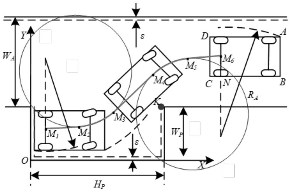
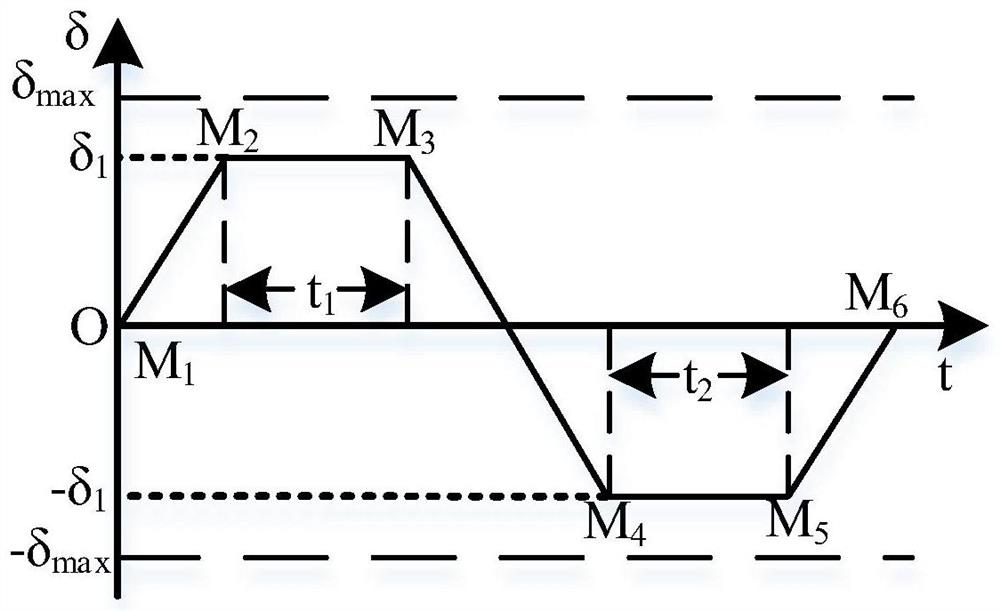
[0040] Establish a parallel parking model such as figure 2 The display, where W A W P , H P And ε are road width, parking space width, parking length and safety distance. For the vehicle system, a certain angle and speed input are given, then the vehicle will move to generate a motion trajectory. According to this feature, combined with the rotation angle and speed change trend, when a given vehicle system is image 3 with Figure 4 The rotation angle and speed input shown will result figure 2 Middle M 1 → M 2 → ... → m 6 Sports trajectory, trajectory start point M 1 The status is: according to image 3 The correlation betw...


PUM


Abstract

The invention discloses a parallel parking trajectory planning method based on a vehicle kinematic model. The method comprises the steps of firstly, establishing a parallel parking geometric model and a vehicle kinematic model according to a vehicle parking scene, and determining a parking point of a vehicle in a target parking space according to the geometric model; secondly, designing the parking speed and the rotating angle according to the speed and rotating angle change trend in the parallel parking process, using the designed speed and rotating angle as vehicle system input, and therefore obtaining a corresponding parking track; and finally, integrating the collision constraint, the vehicle steering performance constraint and the geometric constraint in the parking process, and establishing a target function by taking the minimization of the lateral deviation between the final position and the garage boundary and the rotation angle delta 1, namely the weighted sum of the corresponding track gentle degree and the parking time t as an optimization target to solve the optimal parking track. The parking track designed by the method has the advantages that the geometric collision constraint of the vehicle can be met, the direction angle is smooth, the curvature is continuous and smooth, and the required parking space is small.

Description

Technical field [0001] The present invention relates to parallel parking trajectories, and more particularly to a parallel parking trajectory planning method based on vehicle motion model. Background technique [0002] With the rapid growth of car ownership, not only cause traffic, but the average parking space per car is also gradually narrowed. Small parking spaces have increased difficulty to park operation, which in turn leads to a significant increase in the incidence of traffic safety accidents related to parking. Therefore, research on automatic parking technology can bring huge social benefits. [0003] Automatic parking system key technologies mainly include vehicle positioning, parking detection, trajectory planning and trajectory tracking. The trajectory planning is one of the core work, its goal is to plan a safe collision between the vehicle parking start to the target parking space, meet the vehicle driving trajectory of the vehicle's motion constraint. Traditional ...

Claims


Application Information

Patent Timeline
IPC IPC(8): B60W30/06B60W50/00
CPCB60W30/06B60W50/00B60W2050/0028B60W2050/0031Y02T10/40
Inventor 雷超
Owner SOUTH CHINA UNIV OF TECH
Why Eureka
Try Eureka