Lifting mechanism and sweeper base station
A technology of lifting mechanism and moving parts, which is applied in the direction of lifting frame, lifting device, etc., can solve the problems of complex structure, bulky volume, and large space occupation of the lifting mechanism, and achieve the effect of stable lifting, small size, and reduced occupied space
- Summary
- Abstract
- Description
- Claims
- Application Information
AI Technical Summary
Problems solved by technology
Method used
Image
Examples
Embodiment 1
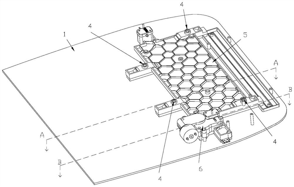
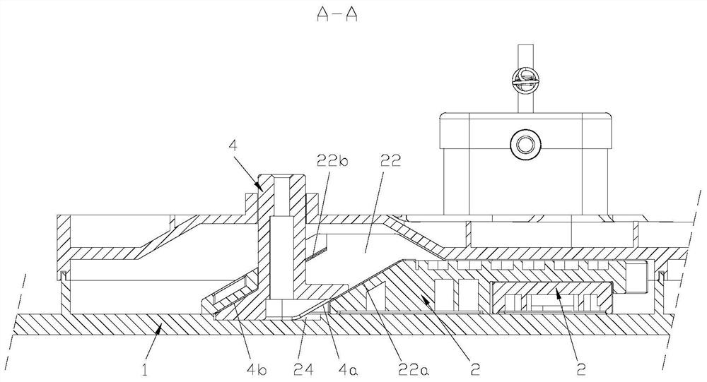
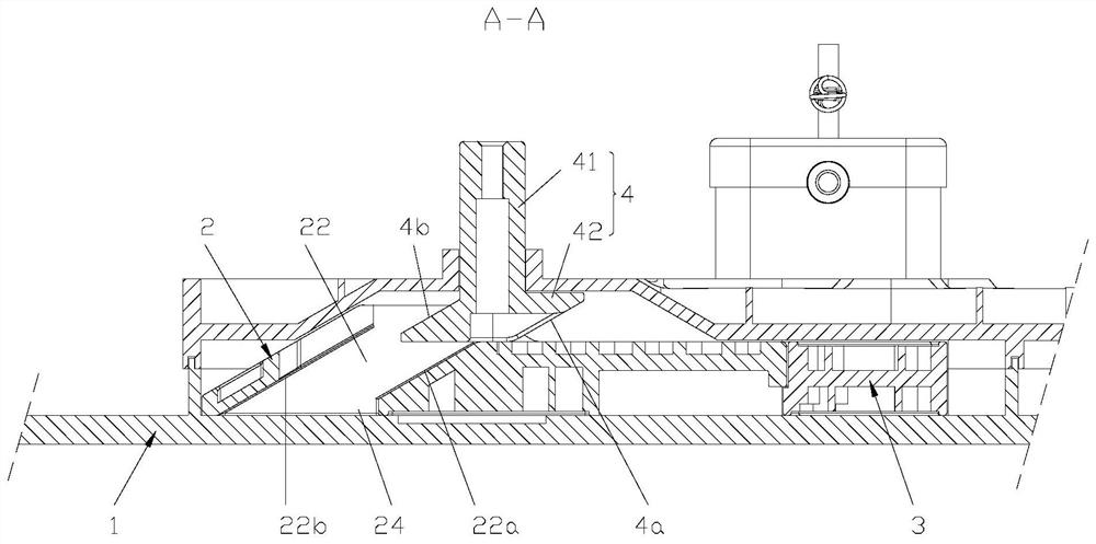
[0039] see Figure 1-3 , the embodiment of the present invention provides a lifting mechanism, including a base 1 , a first moving part 2 , a telescoping part 4 and a fixing part 5 . Wherein, the first moving part 2 is movably arranged on the base 1, the side of the first moving part 2 facing away from the base 1 is provided with a first slope 22a, and the telescopic part 4 is telescopically arranged on the side of the first moving part 2 facing away from the base 1, the telescopic element 4 is provided with a second inclined surface 4a that cooperates with the first inclined surface 22a. When the first moving element 2 moves, the second inclined surface 4a and the first inclined surface 22a move relatively, and the fixing element 5 is fixed on the base 1 And located above the first moving part 2 , the fixing part 5 is provided with a through hole 51 , and the telescopic part 4 is penetrated through the through hole 51 and can move in the through hole 51 .
[0040] Utilize th...
Embodiment 2
[0042] join Figure 2-3 On the basis of Embodiment 1, further, the first moving part 2 is further provided with a third slope 22b on the opposite side of the first slope 22a, and the telescopic member 4 is provided with a fourth slope 4b cooperating with the third slope 22b, The bottoms of the third slope 22b and the fourth slope 4b are arranged at intervals. The third slope 22b is set to cooperate with the fourth slope 4b, so that when the telescopic member 4 extends out of the first moving part 2, the third slope 22b can pull the fourth slope 4b during the movement of the first moving part 2 to make the telescopic part 4 stretch out. 4. The first moving part 2 can be retracted stably and reliably, and the structure is simple and the design is ingenious. The bottoms of the third inclined plane 22b and the fourth inclined plane 4b are arranged at intervals, so that the space between the third inclined plane 22b and the fourth inclined plane 4b is formed when the telescopic el...
Embodiment 3
[0046] see Figure 4-5 , on the basis of the second embodiment, further, the position where the third slope 22b is located is provided with a first avoidance groove 221 for the telescopic element 4 to snap into. In this way, without changing the length of the third slope 22b, the telescopic member 4 can move into the first escape groove 221 when retracting, so as to prevent the third slope 22b from affecting the telescopic stroke of the telescopic member 4 .
PUM
 Abstract
Description
Claims
Application Information
 - R&D
- Intellectual Property
- Life Sciences
- Materials
- Tech Scout
- Unparalleled Data Quality
- Higher Quality Content
- 60% Fewer Hallucinations
Browse by: Latest US Patents, China's latest patents, Technical Efficacy Thesaurus, Application Domain, Technology Topic, Popular Technical Reports.
© 2025 PatSnap. All rights reserved.Legal|Privacy policy|Modern Slavery Act Transparency Statement|Sitemap|About US| Contact US: help@patsnap.com


