Spraying water channel structure and coal mining machine roller
A technology of shearer drum and waterway, which is applied in the direction of cutting machinery, earth drilling and mining, slitting machinery, etc.
- Summary
- Abstract
- Description
- Claims
- Application Information
AI Technical Summary
Problems solved by technology
Method used
Image

Examples
Example Embodiment
[0058] Example 1
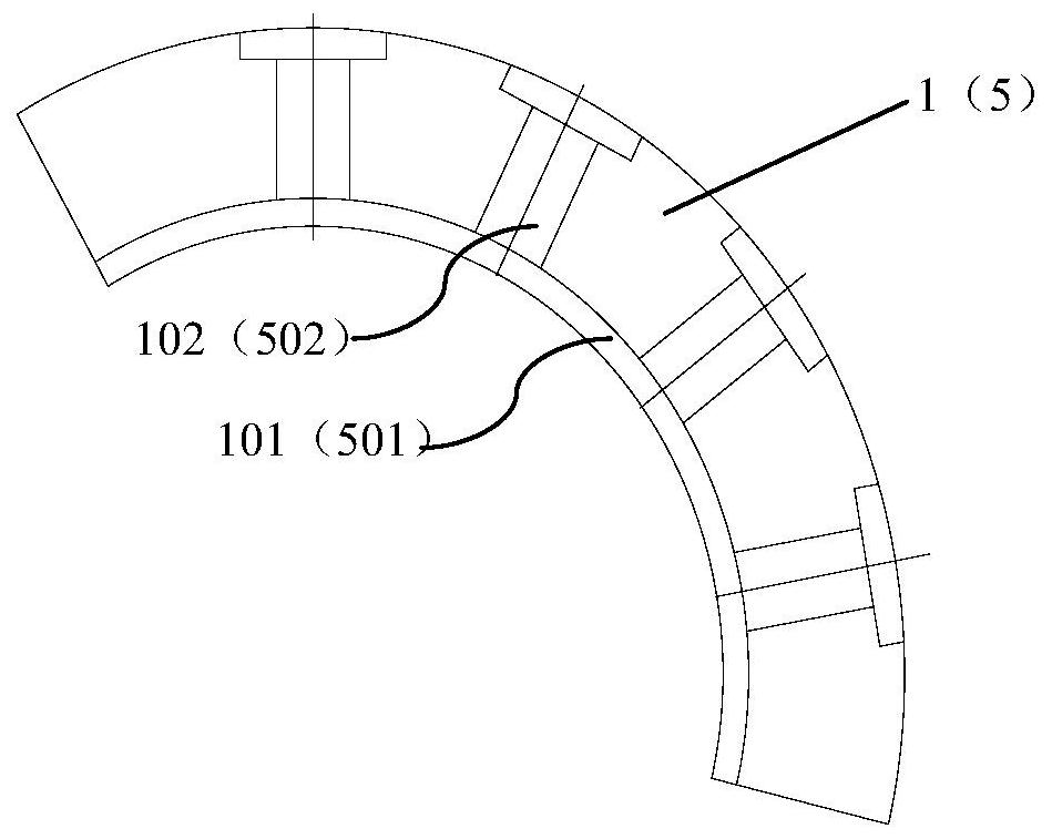
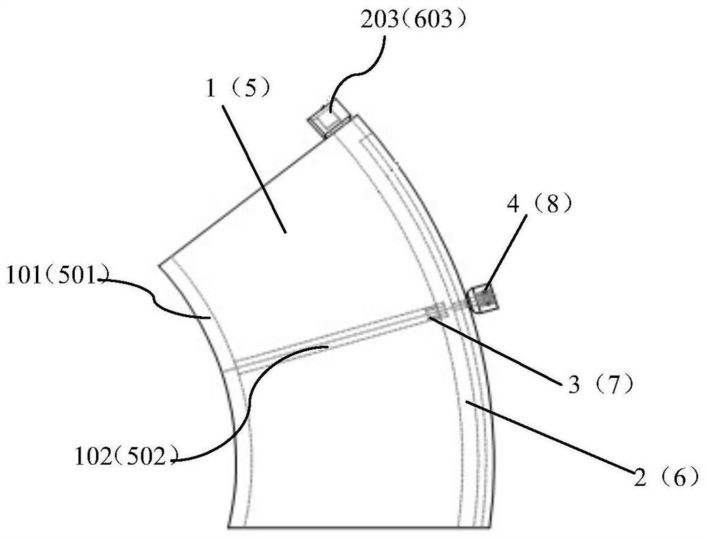
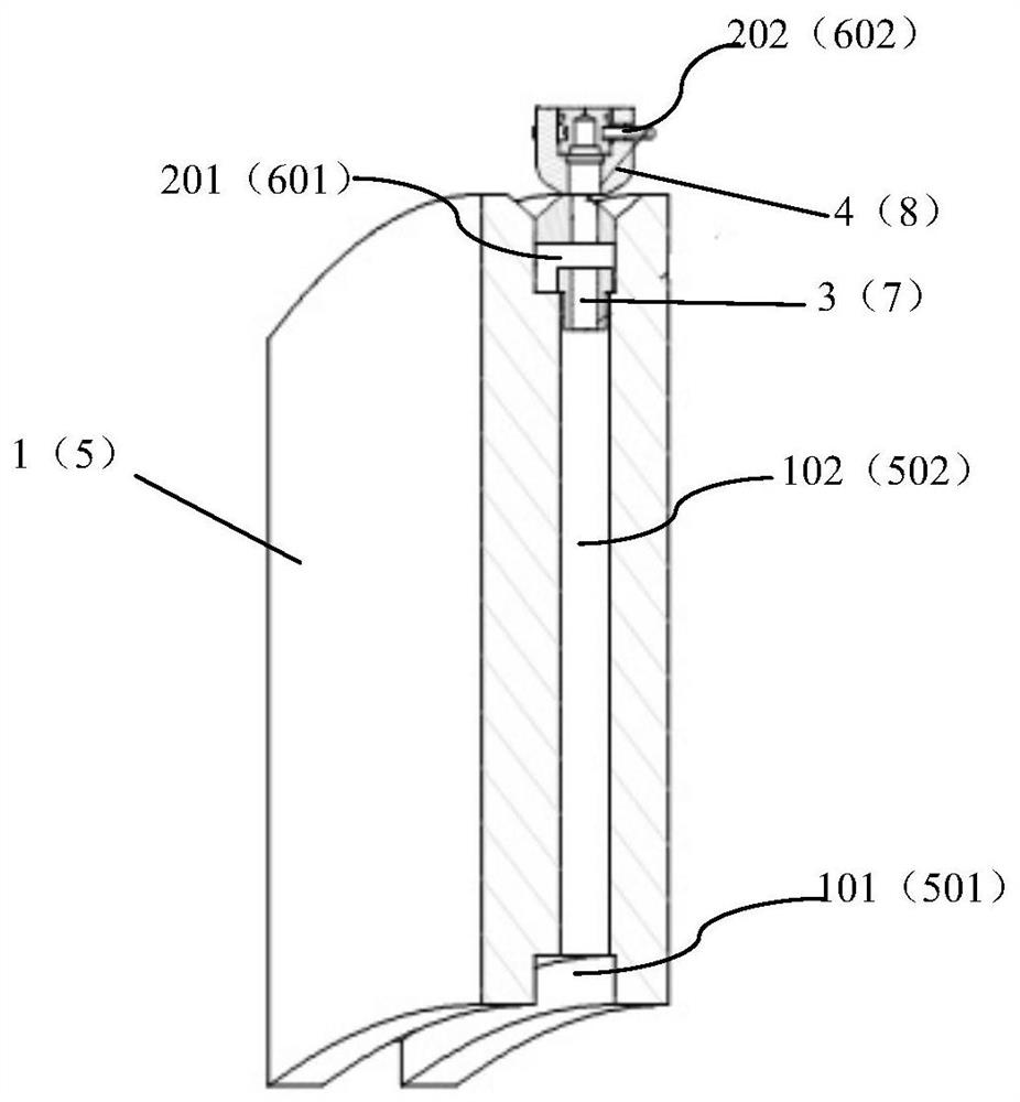
[0059] A spray channel structure provided in this embodiment is applied to a shearer drum. The shearer drum includes a cylinder body 10 and a blade 1 arranged on the cylinder body 10. The spray channel structure includes a blade water channel 101, a first water channel 2, The first radial hole 102, the first one-way valve 3 and the first spray assembly 4, the blade water channel 101 is arranged on the side of the blade 1 adjacent to the cylinder 10; the first water channel 2 is arranged near the outer peripheral end surface of the blade 1; the first diameter The blade waterway 101 and the first waterway 2 are connected to the hole 102; the first one-way valve 3 is arranged in the first radial hole 102, and is used to prevent the water in the first waterway 2 from flowing into the first radial hole 102; the first The spray assembly 4 is arranged on the outer peripheral end surface of the blade 1 and communicated with the first water channel 2 for spraying the...
Example Embodiment
[0066] Example 2
[0067] A spray waterway structure provided in this embodiment is applied to a shearer drum. The shearer drum includes a cylinder body 10 and an end plate 5 arranged on the cylinder body 10. The spray waterway structure includes an end plate waterway 501, a second waterway 6. The second radial hole 502, the second one-way valve 7 and the second spray assembly 8, the end plate water channel 501 is set on the side of the end plate 5 adjacent to the cylinder 10; the second water channel 6 is close to the outer peripheral end surface of the end plate 5 Setting; the second radial hole 502 communicates with the end plate waterway 501 and the second waterway 6; the second one-way valve 7 is arranged in the second radial hole 502 to prevent the water in the second waterway 6 from flowing into the second radial direction In the tunnel 502 ; the second spray assembly 8 is arranged on the outer peripheral end surface of the end plate 5 and communicated with the second w...
Example Embodiment
[0073] Example 3
[0074] A kind of shearer drum provided in this embodiment, see Figure 4 , including cylinder 10, blade 1 and end disk 5, blade 1 is connected to the outer peripheral surface of cylinder 10; end disk 5 is connected to the outer peripheral surface of cylinder 10, and is closer to the end of cylinder 10 than blade 1; this implementation The shearer drum provided in the example also includes the spray channel structure described in Example 1.
[0075]The coal shearer drum provided in this embodiment can ensure that the first radial hole 102 on the blade 1 is not blocked by the blockage in the first water channel 2, and at the same time spray the first spray assembly 4 on the first water channel 2 The water in a waterway 2 is sprayed onto the pick assembly 9 on the shearer drum, thereby ensuring that the first spray assembly 4 cools and removes dust on the pick assembly 9 when the water volume is relatively sufficient.
[0076] Further, the spray waterway stru...
PUM
 Abstract
Description
Claims
Application Information
 - R&D Engineer
- R&D Manager
- IP Professional
- Industry Leading Data Capabilities
- Powerful AI technology
- Patent DNA Extraction
Browse by: Latest US Patents, China's latest patents, Technical Efficacy Thesaurus, Application Domain, Technology Topic.
© 2024 PatSnap. All rights reserved.Legal|Privacy policy|Modern Slavery Act Transparency Statement|Sitemap