Hardware system monitoring method and device
A hardware system and hardware device technology, applied in hardware monitoring, image data processing, 3D modeling, etc., can solve the problems of too little display information of the 2D model, the inability of the operation and maintenance personnel to confirm the relevant parts of the state, etc., and achieve rapid determination The location of the failure and the effect of the state-related parts
- Summary
- Abstract
- Description
- Claims
- Application Information
AI Technical Summary
Problems solved by technology
Method used
Image

Examples
Embodiment 1
[0029] According to an embodiment of the present application, a method embodiment of a hardware system monitoring method is provided. It should be noted that the steps shown in the flow chart of the accompanying drawings can be executed in a computer system such as a set of computer-executable instructions, and , although a logical order is shown in the flowcharts, in some cases the steps shown or described may be performed in an order different from that shown or described herein.
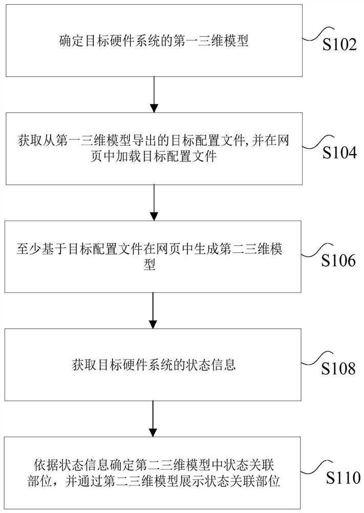
[0030] figure 2 is a hardware system monitoring method according to an embodiment of the present application, such as figure 2 As shown, the method includes the following steps:
[0031] Step S102, determining a first three-dimensional model of the target hardware system, wherein the target hardware system is composed of multiple hardware devices;
[0032] In some embodiments of the present application, determining the first three-dimensional model of the target hardware system includes: estab...
Embodiment 2
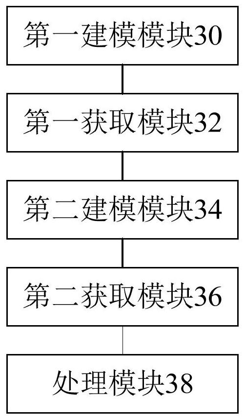
[0076] image 3 is a hardware system monitoring device according to an embodiment of the present application, such as image 3 As shown, the device includes:
[0077] The first modeling module 30 is configured to determine a first three-dimensional model of the target hardware system, wherein the target hardware system is composed of multiple hardware devices;
[0078] The first obtaining module 32 is used to obtain the target configuration file derived from the first three-dimensional model, and load the target configuration file in the webpage;
[0079] A second modeling module 34, at least based on the target configuration file to generate a second three-dimensional model in the webpage;
[0080] The second acquiring module 36 is configured to acquire fault information of the target hardware system;
[0081] The processing module 38 is configured to determine the location of the failure in the second three-dimensional model according to the failure information, and displ...
Embodiment 3
[0085] In some embodiments of the present application, there is also provided a non-volatile storage medium, which is characterized in that the storage medium includes a stored program, wherein when the program is running, the device where the storage medium is located is controlled to execute the above-mentioned Hardware system monitoring method.
[0086] The serial numbers of the above embodiments of the present application are for description only, and do not represent the advantages and disadvantages of the embodiments.
PUM
 Abstract
Description
Claims
Application Information
 - R&D
- Intellectual Property
- Life Sciences
- Materials
- Tech Scout
- Unparalleled Data Quality
- Higher Quality Content
- 60% Fewer Hallucinations
Browse by: Latest US Patents, China's latest patents, Technical Efficacy Thesaurus, Application Domain, Technology Topic, Popular Technical Reports.
© 2025 PatSnap. All rights reserved.Legal|Privacy policy|Modern Slavery Act Transparency Statement|Sitemap|About US| Contact US: help@patsnap.com