
Integrated antenna and electronic equipment

An integrated antenna and feed point technology, applied in antennas, resonant antennas, loop antennas, etc., can solve the problem of narrow bandwidth of low-frequency signals, achieve the effect of widening the low-frequency band and eliminating distributed capacitance

Active Publication Date: 2021-06-11
HANGZHOU HIKVISION DIGITAL TECH
View PDF4 Cites 0 Cited by
  • Summary
  • Abstract
  • Description
  • Claims
  • Application Information

AI Technical Summary

Problems solved by technology

Some integrated antennas can send and receive low-frequency signals, but the bandwidth of the low-frequency signals sent and received is narrow

Method used


Image

  • Integrated antenna and electronic equipment
  • Integrated antenna and electronic equipment
  • Integrated antenna and electronic equipment

Examples


Embodiment Construction

[0031] Reference will now be made in detail to the exemplary embodiments, examples of which are illustrated in the accompanying drawings. When the following description refers to the accompanying drawings, the same numerals in different drawings refer to the same or similar elements unless otherwise indicated. The implementations described in the following exemplary embodiments do not represent all implementations consistent with this application. Rather, they are merely examples of means consistent with aspects of the present application as recited in the appended claims.

[0032] The terminology used in this application is for the purpose of describing particular embodiments only, and is not intended to limit the application. Unless otherwise defined, the technical terms or scientific terms used in the present application shall have the common meanings understood by those skilled in the art to which the present invention belongs. Words such as "one" or "one" used in the sp...


PUM


Abstract

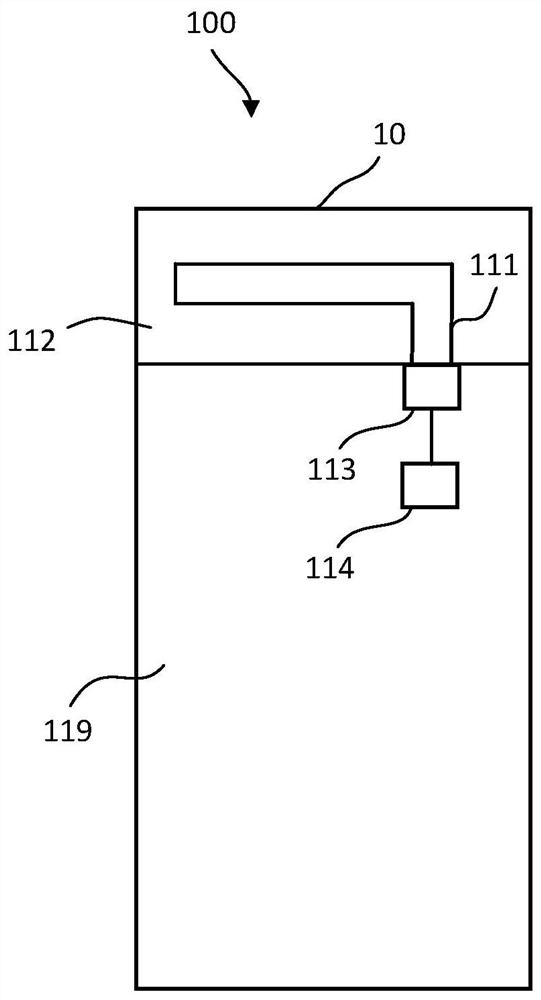
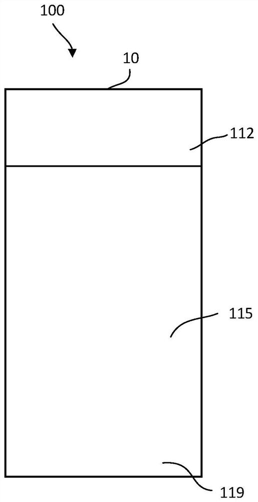
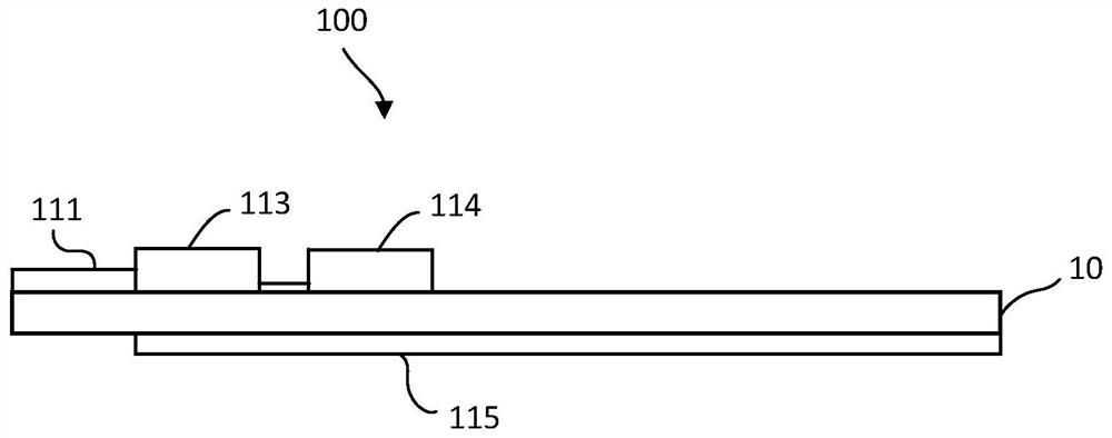
The invention provides an integrated antenna and electronic equipment. The integrated antenna comprises a dielectric substrate, a radiator, a debugging circuit and a paving layer. The dielectric substrate comprises a clearance area, the radiator is arranged in the clearance area, the debugging circuit is arranged in the clearance area, the debugging circuit is connected with the radiator, and the ground paving layer is arranged outside the clearance area of the dielectric substrate. The electronic equipment includes an integrated antenna. The low-frequency bandwidth of the integrated antenna is wide.

Description

technical field [0001] The present application relates to the communication field, in particular to an integrated antenna and electronic equipment. Background technique [0002] With the rapid development of wireless communication and electronic technology, integrated antennas are used more and more widely, and play an important role in many communication fields. Some integrated antennas can transmit and receive low-frequency signals, but the bandwidth of the low-frequency signals transmitted and received is narrow. Contents of the invention [0003] The present application provides an improved integrated antenna and electronic device. [0004] One aspect of the present application provides an integrated antenna comprising: [0005] Dielectric substrates, including clearance areas; [0006] Radiators are arranged in the clearance area; [0007] a debugging circuit, which is arranged in the clear area, and the debugging circuit is connected to the radiator; [0008] Th...

Claims


Application Information

Patent Timeline
Patent Type & Authority Applications(China)
IPC IPC(8): H01Q1/38H01Q1/48H01Q1/50H01Q5/335H01Q7/00H01Q9/30
CPCH01Q1/38H01Q1/48H01Q1/50H01Q5/335H01Q7/00H01Q9/30
Inventor 董怀景
Owner HANGZHOU HIKVISION DIGITAL TECH
Learn More