
Rotor iron core axial clamping assembly, rotor and motor

A technology of rotor core and clamping components, applied in the direction of magnetic circuit rotating parts, magnetic circuit shape/style/structure, etc., can solve the negative effects of electromagnetic flow, the consistency of pressing and positioning of the core lamination group is difficult to guarantee, Due to the large size deviation of the iron core lamination group, the effects of reducing the dynamic unbalance of the rotor, simple and reliable clamping, and reducing the difficulty of installation are achieved.

Pending Publication Date: 2021-06-11
慕贝尔汽车部件(太仓)有限公司
View PDF0 Cites 0 Cited by
  • Summary
  • Abstract
  • Description
  • Claims
  • Application Information

AI Technical Summary

Problems solved by technology

Since the bolts need to penetrate the rotor core (core laminations), not only the assembly is cumbersome, time-consuming and labor-intensive, but also has a negative impact on the electromagnetic flow, and requires high dimensional accuracy of the parts, resulting in the compression and positioning of the core laminations. The consistency is difficult to guarantee, resulting in a large size deviation of the iron core stack, resulting in a large dynamic unbalance of the rotor

Method used


Image

  • Rotor iron core axial clamping assembly, rotor and motor
  • Rotor iron core axial clamping assembly, rotor and motor
  • Rotor iron core axial clamping assembly, rotor and motor

Examples


Embodiment Construction

[0038] In order to make the technical problems, technical solutions and beneficial effects to be solved by the present invention clearer, the present invention will be further described in detail below in conjunction with the accompanying drawings and embodiments. It should be understood that the specific embodiments described here are only used to explain the present invention, not to limit the present invention.

[0039] It should be noted that when an element is referred to as being “connected to” or “disposed on” another element, it may be directly on the other element or be indirectly on the other element. When an element is referred to as being "connected to" another element, it can be directly connected to the other element or indirectly connected to the other element.

[0040] In the description of the present invention, it should be noted that unless otherwise specified and limited, the terms "installation", "connection" and "connection" should be understood in a broa...


PUM


Abstract

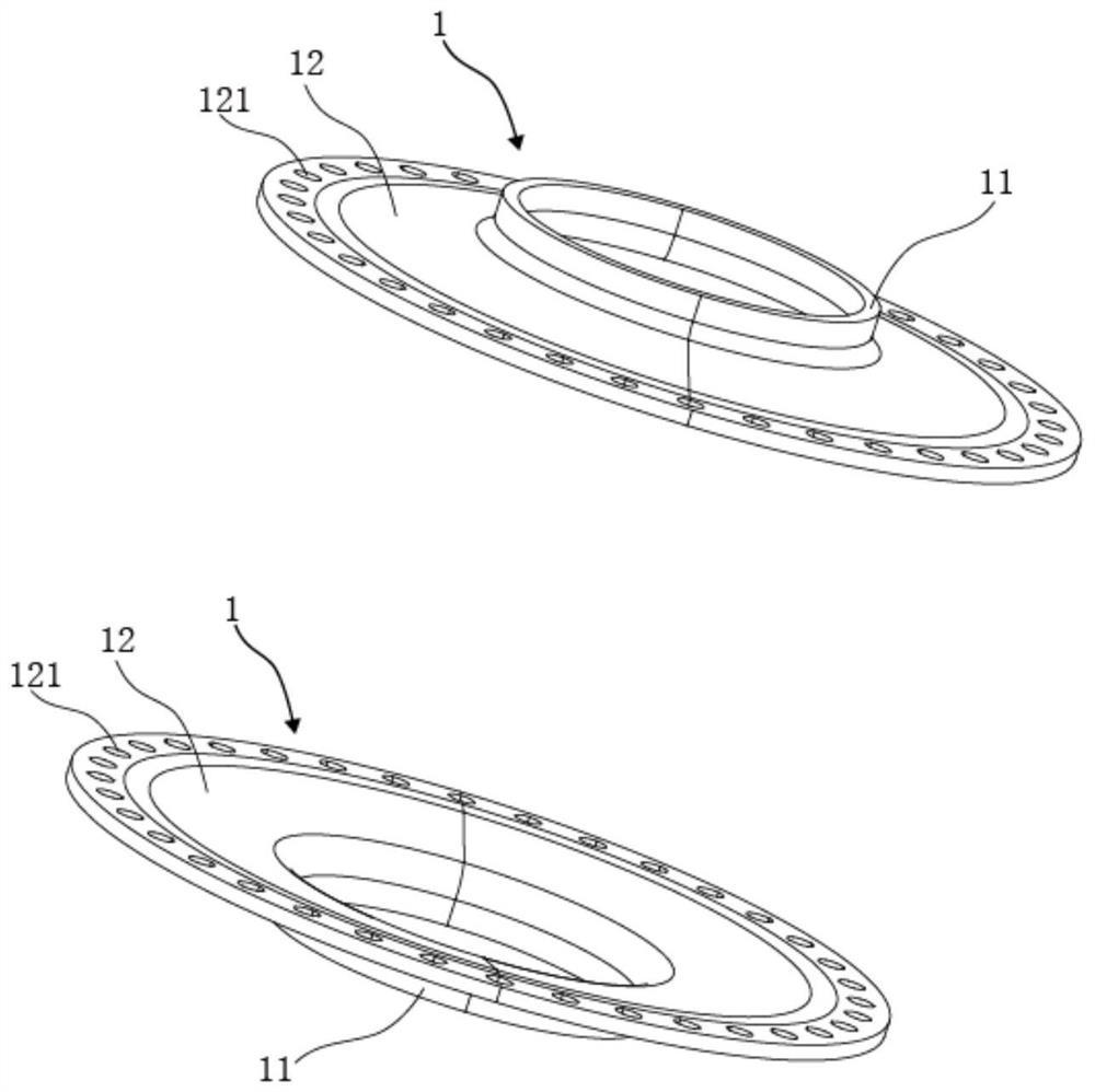
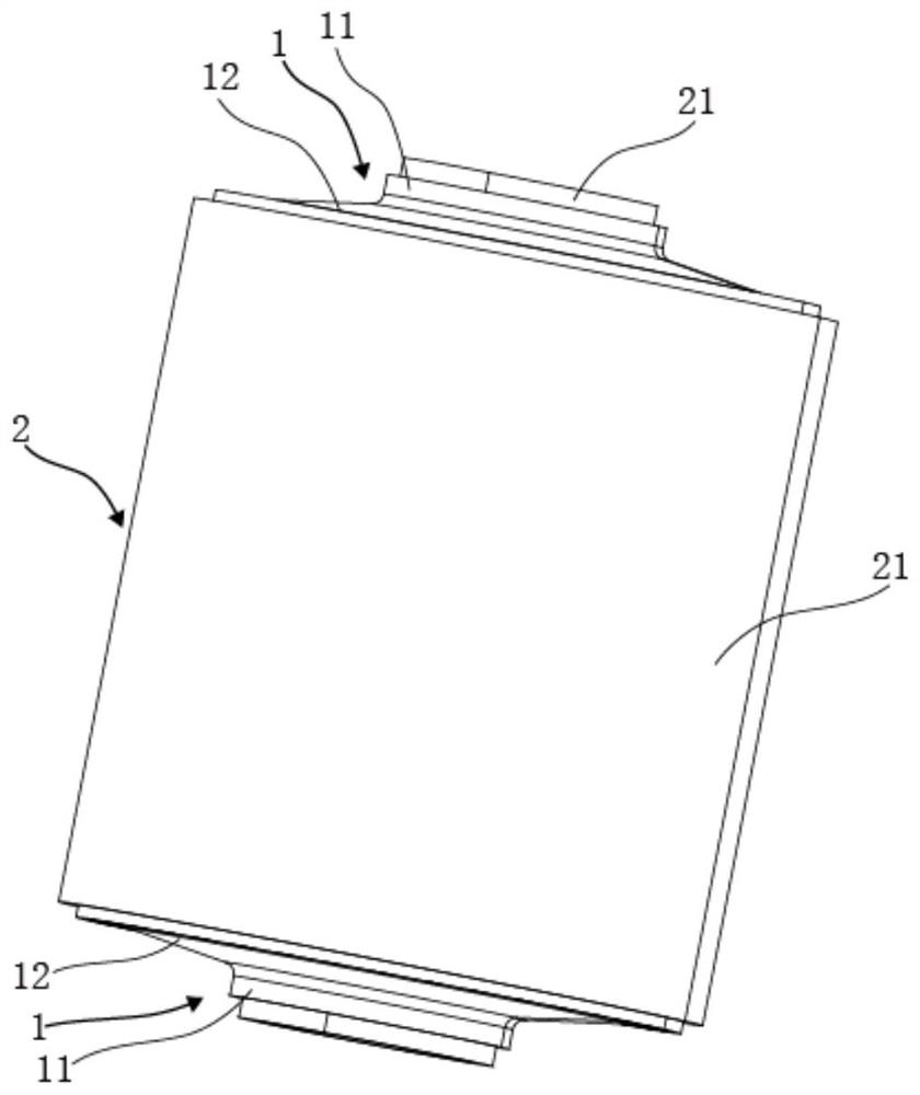
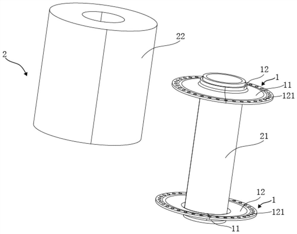
The invention provides a rotor iron core axial clamping assembly, a rotor and a motor. The rotor iron core axial clamping assembly comprises two clamping elements arranged in pairs,wherein each clamping element comprises a circular sleeve and an abutting ring extending outwards from one end of the circular sleeve in the radial direction of the circular sleeve, each circular sleeve is used for sleeving and fixing a rotor shaft, and the two abutting rings are used for abutting against the end faces of the two axial ends of a rotor iron core respectively. During use, the circular sleeve of each clamping element sleeves and is fixed on the rotor shaft, so that the rotor core is clamped between the abutting rings of the two clamping elements, the two abutting rings are respectively pressed against and tightly pressed on the end surfaces of the two axial ends of the rotor core, an elastic force can be generated in the axial direction so as to ensure a simple and reliable clamping effect on the rotor iron core, and enough tolerance can be provided for size errors caused in the rotor production process and deformation and creep generated in the operation process in the axial direction of the rotor shaft.

Description

technical field [0001] The invention belongs to the technical field of electric drive equipment, and in particular relates to a rotor iron core axial clamping assembly, a rotor and a motor. Background technique [0002] The rotor of the motor includes a rotor shaft and a rotor core fixed on the rotor shaft. The rotor core is generally an iron core stack formed by lamination of steel sheets along the axial direction of the rotor shaft. At present, in the case of no axial compression of the iron core laminations, it is easy to loosen during the working process of the rotor. Therefore, it is usually necessary to configure additional bolts and nuts, and the bolts are sequentially passed through the iron core along the axial direction of the rotor shaft. The steel sheets of the core laminations are locked with nuts to provide axial compressive force to the core laminations. Since the bolts need to penetrate the rotor core (core laminations), not only the assembly is cumbersome, ...

Claims


Application Information

Patent Timeline
IPC IPC(8): H02K1/28
CPCH02K1/28
Inventor 本杰明·登格斯马克西米利安·罗尔费斯
Owner 慕贝尔汽车部件(太仓)有限公司
Learn More