Needle plate ball screening machine

A ball screening machine and needle plate technology, applied in the field of ball screening equipment, can solve the problems of extensive screening methods and inability to screen steel balls, and achieve the effects of improving grinding effect and screening accuracy.

Inactive Publication Date: 2021-06-15
唐山冀东启新水泥有限责任公司
View PDF0 Cites 0 Cited by
  • Summary
  • Abstract
  • Description
  • Claims
  • Application Information

AI Technical Summary

Problems solved by technology

These screening devices have two common shortcomings: (1) The screening method is relatively extensive, so it is impossible to accurately screen out steel balls with a diameter error of less than 1mm; (2) It is impossible to accurately screen out steel balls with unqualified roundness. sift out

Method used


Image

  • Needle plate ball screening machine
  • Needle plate ball screening machine
  • Needle plate ball screening machine

Examples


Embodiment 1

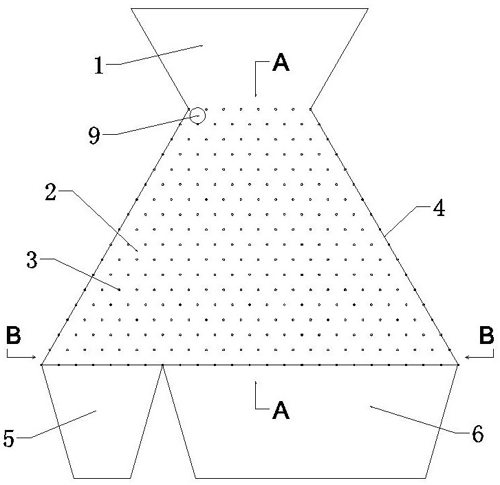
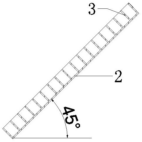
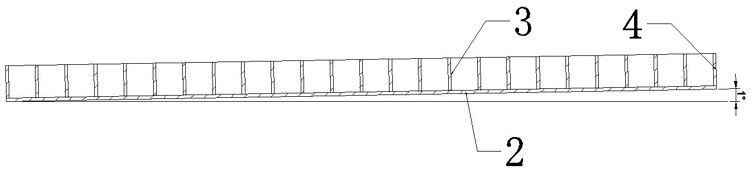
[0022] see Figure 2 to Figure 4 , when it is necessary to sieve to obtain steel balls with a diameter of 8.70mm, the distance between the fixed points at the lower ends of the striker 3 is 9mm, the inclination angle of the bottom plate 2 in the vertical direction is 45°, and the left and right inclination angle of the bottom plate 2 is 1° (the left side is lower, the right side is lower). Side height), at this time, the maximum diameter of the sphere that can pass between the striker 3 rods is 8.70mm. Other structures of the needle plate ball sieving machine remain unchanged. The balls to be screened 9 enter the needle plate ball screening machine from the feeding chute 1, and the steel balls with a diameter of 8.70mm are affected by the left and right inclinations of the bottom plate 2. The trajectory of the impact movement is leftward, and finally falls into the left finished product groove 5 Inside, the steel ball with a diameter of less than 8.70mm enters the second floo...

Embodiment 2

[0024] see figure figure 2 with Figure 5 , when it is necessary to sieve to obtain steel balls with a diameter of 8.38 mm, the distance between the fixed points at the lower end of the firing pin 3 is 9 mm, the bottom plate 2 is tilted 45° in the vertical direction, and the bottom plate 2 is tilted left and right by 2° (lower on the left side and higher on the right side). The maximum diameter of the sphere that can pass between the striker 3 rods is 8.38mm. The other structures of the needle-plate ball sieving machine remain unchanged, and the sieving process is the same as that of Example 1. Finally, steel balls with a diameter of 8.38 mm are obtained to achieve precise sieving.

Embodiment 3

[0026] see figure 2 with Figure 6 , when it is necessary to sieve to obtain steel balls with a diameter of 8.08mm, the distance between the fixed points at the lower end of the striker 3 is 9mm, the bottom plate 2 is tilted 45° in the vertical direction, and the bottom plate 2 is tilted left and right by 3° (lower on the left side and higher on the right side). The maximum diameter of the sphere that can pass between the striker 3 sticks is 8.08mm. The other structures of the needle-plate ball sieving machine remain unchanged, and the sieving process is the same as that of Example 1. Finally, steel balls with a diameter of 8.08 mm are obtained to achieve precise sieving.


PUM


Abstract

The invention discloses a needle plate ball screening machine, and relates to the field of ball screening equipment. The needle plate ball screening machine comprises a feeding chute, a screening area and a discharging chute. The screening area comprises a bottom plate, firing pins and side plates, the bottom plate is of a trapezoidal structure, the firing pins are evenly fixed to the upper surface of the bottom plate, and the two side edges of the bottom plate are fixedly connected with the side plates correspondingly; the upper end of the bottom plate is connected with the feeding chute, and the lower end of the bottom plate is connected with the discharging chute; and the bottom plate is obliquely arranged in the vertical direction and the left-right direction, and a supporting frame is arranged on the lower end face of the bottom plate. According to the needle plate ball screening machine, precise screening of balls is carried out through the inclination angle of a needle plate, and finished balls with a certain specific particle size are obtained through screening, so that the screening precision of the balls is improved, the needle plate ball screening machine is suitable for secondary fine screening of the balls, and the grinding effect of a ball mill is improved.

Description

technical field [0001] The invention relates to the field of ball screening equipment, in particular to a needle plate ball screening machine. Background technique [0002] In the cement production process, semi-finished cement is ground into finished cement by cement ball mill. The grinding body inside the ball mill is mainly steel balls, which will wear out with time. If the steel ball wear exceeds a certain percentage, it will affect the quality of the cement produced. For this reason, the steel balls need to be screened regularly. The sorting technologies commonly used in the market are roughly divided into three categories: (1) air sorting method: use the wind energy of the cyclone to stratify the materials step by step, and then collect them into different devices; (2) gravity sorting method: use The gravity of the material causes the material to be layered step by step, and then collected into different devices. The commonly used gravity separation method is divide...

Claims


Application Information

Patent Timeline
Patent Type & Authority Applications(China)
IPC IPC(8): B07B13/04B07B13/14
CPCB07B13/04B07B13/14
Inventor 刘洋谢荣华史东海鲁铜王安伟唐贺丰冯凯张健吴俊良师瑞山
Owner 唐山冀东启新水泥有限责任公司
Why Eureka
Try Eureka