A kind of instrument cleaning equipment for industrial chemistry

A cleaning equipment and chemical technology, applied in the chemical field of industry, can solve the problems of outer wall dissection, affecting the reuse of test tubes, etc., and achieve the effect of speeding up cleaning and reducing friction.

Active Publication Date: 2022-06-07
山东秋淇分析仪器有限公司
View PDF0 Cites 0 Cited by
  • Summary
  • Abstract
  • Description
  • Claims
  • Application Information

AI Technical Summary

Problems solved by technology

[0002] After the chemical test tube is used, because some chemical reagents are solidified on the inner wall of the test tube, the test tube is cleaned by a washing machine, and the test tube is put into the cleaning tank of the washing machine, and then the cleaning solution is sent to the cleaning tank through the water pipe, and the test tube is soaked and cleaned; now In the prior art, when a cleaning machine is used to clean the test tubes, due to the light weight of the test tubes, when the liquid is passed into the cleaning tank, the test tubes are floated in the cleaning tank by the buoyancy of the liquid, causing the test tubes to collide with each other and the outer wall to be damaged. reuse of test tubes

Method used


Image

  • A kind of instrument cleaning equipment for industrial chemistry
  • A kind of instrument cleaning equipment for industrial chemistry
  • A kind of instrument cleaning equipment for industrial chemistry

Examples


Embodiment 1

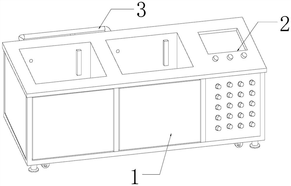
[0027] as attached figure 1 to the attached Image 6 shown:

[0028] The present invention provides an industrial chemical instrument cleaning device, which comprises a body 1, a control panel 2, and a water delivery pipe 3. The control panel 2 is arranged on the upper surface of the right end of the body 1, and the water delivery pipe 3 is installed on the back of the body 1.

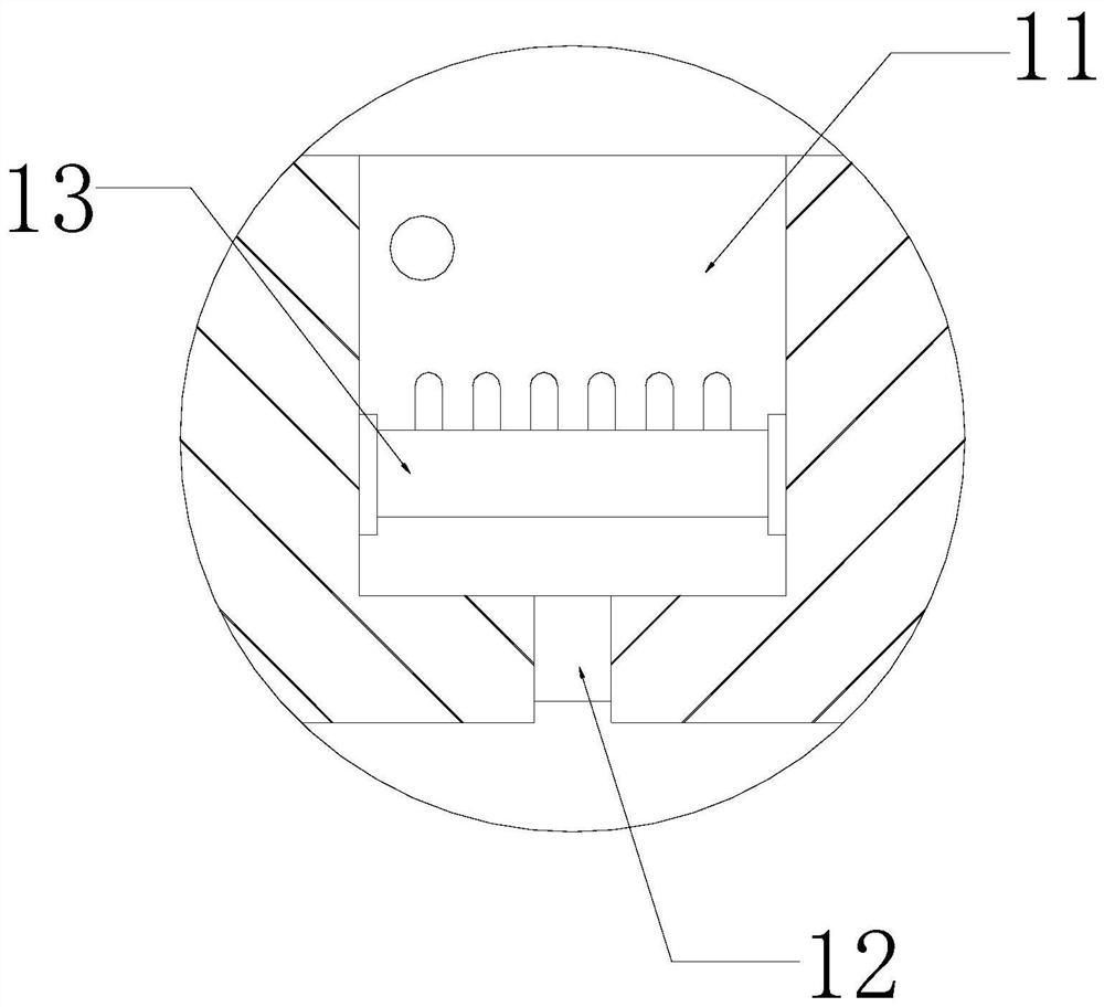
[0029] The body 1 is provided with a cleaning tank 11, a drain port 12, and a limiting mechanism 13. The cleaning tank 11 is provided inside the body 1, and the drain port 12 penetrates the bottom surface of the body 1 and communicates with the cleaning tank 11. The The limiting mechanism 13 is installed on the inner wall of the cleaning tank 11 .

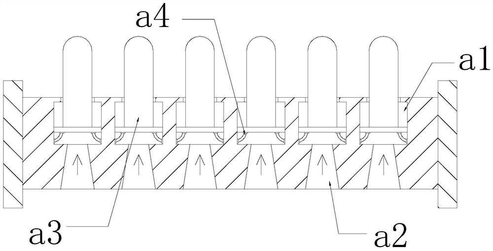
[0030] The limiting mechanism 13 is provided with a stacking cavity a1, a water inlet a2, a support tube a3, and a reset bar a4, the stacking cavity a1 is set inside the upper position of the limiting mechanism 13, and the water inlet a2 passes through th...

Embodiment 2

[0037] as attached Figure 7 to the attached Figure 8 shown:

[0038] The water inlet a2 is provided with a clamping plate r1, a connecting shaft r2, and a push rod r3. The bottom end of the clamping plate r1 is connected to the inner wall of the middle and lower part of the water inlet a2 through the connecting shaft r2, and the push rod r3 is horizontally fixed on the inner wall of the water inlet a2. Between the top side of the card plate r1 and the inner wall of the water inlet a2, there are two card plates r1, which are symmetrically distributed, which is conducive to the active cooperation between the card plate r1 and the liquid, and can block the liquid, so that the amount of liquid in the accumulation chamber a1 change, and the thrust received by the support tube a3 decreases and moves up and down, which is beneficial for the cleaning tube s3 to continuously rub against the inner wall of the test tube and speed up the cleaning of the test tube.

[0039] The card bo...


PUM


Abstract

The invention discloses an instrument cleaning device for industrial chemistry. The structure includes a machine body, a control panel and a water delivery pipe. Since the test tube is light in weight, when the liquid is passed into the cleaning tank, the test tube floats in the cleaning tank under the buoyancy of the liquid. The test tube is supported and limited by the support tube of the limit mechanism, and at the same time, the dirt on the inner wall of the test tube is cleaned by the cleaning tube, which can keep the inner wall of the test tube clean and tidy, and reduce the test tube floating in the cleaning tank by the buoyancy of the liquid, and reduce the impact of the test tubes on the outer wall. The phenomenon of dissection is conducive to the reuse of the test tube. Since the thrust of the liquid in the accumulation chamber remains unchanged, the support tube is kept still, and the friction between the cleaning tube and the inner wall of the test tube is reduced. Blocking the liquid is beneficial to change the amount of liquid inside the accumulation chamber, while the thrust received by the support tube is reduced to move up and down, which is conducive to the continuous friction of the cleaning tube with the inner wall of the test tube and speeds up the cleaning of the test tube.

Description

technical field [0001] The invention belongs to the field of chemistry in the industrial aspect, and more specifically, relates to an instrument cleaning device for industrial chemistry. Background technique [0002] After the chemical test tube is used, since some chemical reagents are solidified on the inner wall of the test tube, the test tube is cleaned with a cleaning machine, and the test tube is put into the cleaning tank of the cleaning machine, and then the cleaning solution is sent to the cleaning tank through the water pipe, and the test tube is soaked and cleaned; In the prior art, when a cleaning machine is used to clean the test tube, due to the light weight of the test tube, when the liquid is passed into the cleaning tank, the test tube is floated in the cleaning tank by the buoyancy of the liquid, causing the test tubes to collide with each other and the outer wall appears torn. Reuse of test tubes. SUMMARY OF THE INVENTION [0003] In order to solve the ...

Claims


Application Information

Patent Timeline
Patent Type & Authority Patents(China)
IPC IPC(8): B08B9/20B08B9/36
CPCB08B9/20B08B9/36
Inventor 陈明
Owner 山东秋淇分析仪器有限公司
Why Eureka
Try Eureka