Supercharge Your Innovation With Domain-Expert AI Agents!

A tool for automatic bending of galvanized steel pipe and its application method

A galvanized steel pipe, automatic technology, applied in the field of building construction, can solve the problems of difficult management, economic loss, lack of pipe bending tools, etc., and achieve the effect of convenient operation, simple operation and strong flexibility

Active Publication Date: 2022-05-13
CHINA MCC17 GRP
View PDF12 Cites 0 Cited by
  • Summary
  • Abstract
  • Description
  • Claims
  • Application Information

AI Technical Summary

Problems solved by technology

Since the construction site is usually very large, the construction personnel are many and miscellaneous, and the management is difficult. Therefore, if a well-made pipe bending machine is used, it is inconvenient to move due to the heavy equipment and it is easy to cause mechanical damage due to use or improper storage. Economic loss, lack of a portable and efficient pipe bending tool

Method used


Image

  • A tool for automatic bending of galvanized steel pipe and its application method
  • A tool for automatic bending of galvanized steel pipe and its application method
  • A tool for automatic bending of galvanized steel pipe and its application method

Examples


Embodiment 1

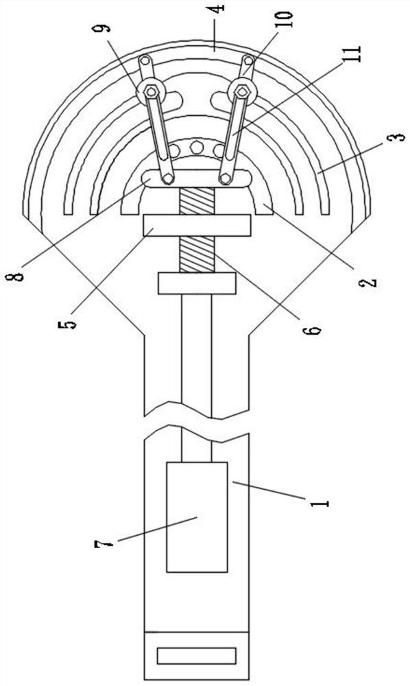
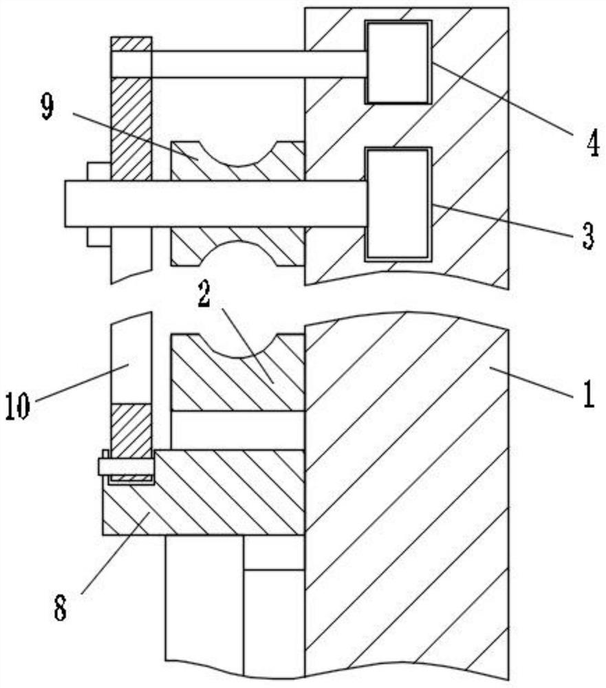
[0026] Such as figure 1 and image 3 As shown, a tool that facilitates automatic bending of galvanized steel pipes includes a body 1 with a hand-held portion, and the body 1 is provided with a forming portion 2, a positioning piece 5, a guide groove 2 4 and a plurality of guide grooves 1 3, A transmission screw 6 is rotatably installed on the positioning member 5, a connector 8 is rotatably installed on one end of the transmission screw 6, and a driver 7 is connected to the other end (the motor and the connecting rod connected to the output end and used to connect the transmission screw 6) , the driver 7 is installed close to the hand-held part, and two guide rods 10 arranged in a figure-eight shape are rotatably installed on the connector 8, and the end of the guide rod 10 away from the connector 8 is movably arranged in the guide groove 2 4 Inside, the two guide rods 10 are provided with chute 11, and the inside of the two chute 11 is provided with a pressure member 9 which...

Embodiment 2

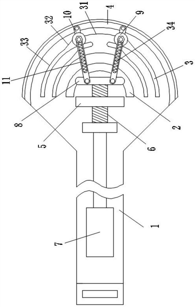
[0035] in such as figure 2 and Figure 4 As shown, the difference from Embodiment 1 is that each of the guide grooves 3 includes a separation part 31, a guide part 32 and a pressurizing part 33, and the two ends of the guide part 32 are connected with the separation part 31 and the pressurizing part respectively. The part 33 communicates, the side wall of the separating part 31 away from the connecting part 8 is located outside the side wall of the pressurizing part 33 away from the connecting part 8, and the side wall of the separating part 31 close to the connecting part 8 and the pressurizing part 33 is coplanar with the side wall near the connector 8. The setting of the separation part 31 is more convenient to separate the pressure member 9 from the steel pipe. If there is no such setting, the operation will be relatively troublesome.

[0036] In a further preferred solution of the present invention, a flat spring 34 is arranged inside the chute 11 , one end of the fla...

Embodiment 3

[0038] Such as figure 2 and Figure 4 As shown, a method for using a tool that facilitates the automatic bending of galvanized steel pipes includes the following steps:

[0039] Step 1: First adjust the pressure part 9 to be inside the guide groove 13 adapted to the diameter of the steel pipe, then insert the steel pipe between the pressure part 9 and the forming part 2, and between the guide rod 10, the connecting part 8 and the body 1 The steel pipe breaks away from the inside of the area;

[0040] Step 2: Start the driver 7, the driver 7 drives the transmission screw 6 to rotate, and then drives the connecting piece 8 to move outward, the end of the guide rod 10 away from the connecting piece 8 expands to both sides along the guide groove 2 4, and the pressure member 9 also follows the guide rod The rotation of 10 moves along the separation part 31, the guide part 32, and the pressurizing part 33 in sequence, and then applies pressure to the steel pipe to bend and form t...


PUM


Abstract

The invention discloses a tool for automatically bending a galvanized steel pipe and a using method thereof, which belong to the field of building construction. It includes a body with a hand-held part. The body is provided with a forming part, a positioning piece, a guide groove 2 and a plurality of guide grooves 1. A transmission screw is installed on the positioning piece. One end of the transmission screw is rotated and installed with a connecting piece, and the other end is connected to There is a driver, and the driver is installed close to the hand-held part. Two guide rods arranged in a figure-eight shape are rotatably installed on the connecting piece. The chute, the inside of the two chute is equipped with a pressure part that is located in the same plane as the forming part, each guide groove 1 is an arc-shaped structure that coincides with the center of the circle, and each guide groove 1 communicates with each other, and the guide groove 2 is set on the The outer side of the first guide groove has an arc-shaped structure, and the pressure member is movably arranged inside the corresponding first guide groove. The invention has the advantages of simple operation, high efficiency, portability and strong flexibility.

Description

technical field [0001] The invention relates to the technical field of building construction, in particular to a tool for facilitating automatic bending of galvanized steel pipes and a use method thereof. Background technique [0002] Construction site installation engineering construction usually needs to bend the steel pipe into the required angle. Since the construction site is usually very large, the construction personnel are many and miscellaneous, and the management is difficult. Therefore, if a well-made pipe bending machine is used, it is inconvenient to move due to the heavy equipment and it is easy to cause mechanical damage due to use or poor storage. Economic loss lacks a portable and efficient pipe bending tool. Contents of the invention [0003] The purpose of the present invention is to solve the deficiencies in the prior art, so it proposes a tool for automatic bending of galvanized steel pipes and a method of use. [0004] In order to achieve the above ...

Claims


Application Information

Patent Timeline
Patent Type & Authority Patents(China)
IPC IPC(8): B21D7/06B21D7/16
CPCB21D7/063B21D7/162
Inventor 夏林峰
Owner CHINA MCC17 GRP
Features
  • R&D
  • Intellectual Property
  • Life Sciences
  • Materials
  • Tech Scout
  • Unparalleled Data Quality
  • Higher Quality Content
  • 60% Fewer Hallucinations
Learn More