Device for carrying out molding pin arrangement on inductor

A technology of inductors and forming mechanisms, which is used in the manufacture of inductors/transformers/magnets, circuits, electrical components, etc., can solve the problems of difficulty in inserting the copper wire of the PIN pin of the inductor, high cost, and difficulty at the bottom of the magnetic core. The effect of smooth tangent, good forming consistency and high yield

Inactive Publication Date: 2021-06-15
WUHAN CHENYANG ELECTRONICS TECH
View PDF10 Cites 1 Cited by
  • Summary
  • Abstract
  • Description
  • Claims
  • Application Information

AI Technical Summary

Problems solved by technology

[0002] Inductors can convert electrical energy into magnetic energy and store them, usually including a magnetic core and lead wires wound on the magnetic core. Cut off the copper wire passing through the cutting corner hole manually, and then take it out and install it on the bottom plate. However, it is difficult to insert the PIN pin copper wire on the inductor into the corresponding bottom plate hole after forming, and it is difficult to stick the bottom of the magnetic core to the base. , Need glue to fix the magnetic core and the base, but the baking and drying process after glue dispensing will make the bottom plate warped and deformed, resulting in a low yield of inductors, high cost, and a cumbersome preparation process

Method used


Image

  • Device for carrying out molding pin arrangement on inductor
  • Device for carrying out molding pin arrangement on inductor
  • Device for carrying out molding pin arrangement on inductor

Examples


Embodiment Construction

[0018] Embodiments of the present invention will be described in further detail below in conjunction with the accompanying drawings.

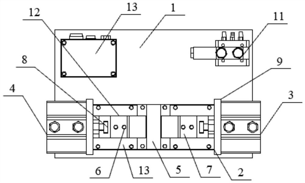
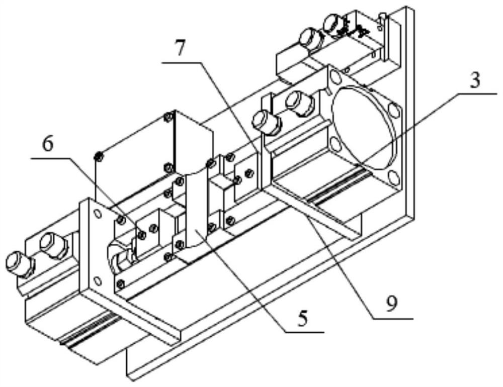
[0019] see figure 1 and figure 2 As shown, the embodiment of the present invention provides a device for forming and trimming inductors, including a mounting base 1, on which a cutting leg forming mechanism 2, an electric control switch box 14 and a pneumatic control valve 11 are arranged. The first cylinder 3 and the second cylinder 4 are arranged on both sides of the shearing foot forming mechanism 2, and the first cylinder 3, the second cylinder 4, and the pneumatic control valve 11 are all electrically connected with the electric control switch box 14.

[0020] The shearing foot molding mechanism 2 comprises a magnetic core accommodation area 5, a first molding briquetting block 6 and a second molding briquetting block 7, and the first molding briquetting block 6 and the second molding briquetting block 7 are distributed on both sides of ...


PUM


Abstract

The invention discloses a device for carrying out molding pin arrangement on an inductor and relates to the field of inductor manufacturing. The device comprises a mounting bottom plate; a pin cutting forming mechanism is arranged on the mounting bottom plate; a first air cylinder and a second air cylinder are arranged on the two sides of the pin cutting forming mechanism; the pin cutting forming mechanism comprises a magnetic core containing area, a first forming pressing block and a second forming pressing block; the first forming pressing block and the second forming pressing block are distributed on the two sides of the magnetic core containing area; pin cutters are arranged on the sides, away from the magnetic core containing area, of the first forming pressing block and the second forming pressing block correspondingly; and the pin cutters are connected with the first air cylinder and the second air cylinder correspondingly through an air cylinder fixing plate. The method can improve the yield and reduce the production cost.

Description

technical field [0001] The invention relates to the field of manufacturing inductors, in particular to a device for forming and trimming inductors. Background technique [0002] Inductors can convert electrical energy into magnetic energy and store them, usually including a magnetic core and lead wires wound on the magnetic core. Cut off the copper wire passing through the cutting corner hole manually, and then take it out and install it on the bottom plate. However, it is difficult to insert the PIN pin copper wire on the inductor into the corresponding bottom plate hole after forming, and it is difficult to stick the bottom of the magnetic core to the base. , Need glue to fix the magnetic core and the base, but the baking and drying process after glue dispensing will cause the bottom plate to warp and deform, resulting in a low yield of the inductor, high cost, and a cumbersome preparation process. Contents of the invention [0003] Aiming at the defects existing in the...

Claims


Application Information

Patent Timeline
Patent Type & Authority Applications(China)
IPC IPC(8): B21F1/02B21F11/00H01F41/00
CPCB21F1/026B21F11/00H01F41/00
Inventor 程登峰程家忠
Owner WUHAN CHENYANG ELECTRONICS TECH
Why Eureka
Try Eureka