
Deformable wing and deformation method

A wing, No. 1 technology, applied in the field of deformable wings and deformation, can solve the problems that affect the flight safety of aircraft, severe wing flutter, etc., and achieve the effect of good adjustment flexibility, large transmission ratio, and reduced speed

Active Publication Date: 2021-06-15
SHANGHAI UNIV OF ENG SCI
View PDF5 Cites 2 Cited by
  • Summary
  • Abstract
  • Description
  • Claims
  • Application Information

AI Technical Summary

Problems solved by technology

When the speed is too high, the flutter of a single wing with a large aspect ratio is severe, which affects the flight safety of the aircraft

Method used


Image

  • Deformable wing and deformation method
  • Deformable wing and deformation method
  • Deformable wing and deformation method

Examples


Embodiment Construction

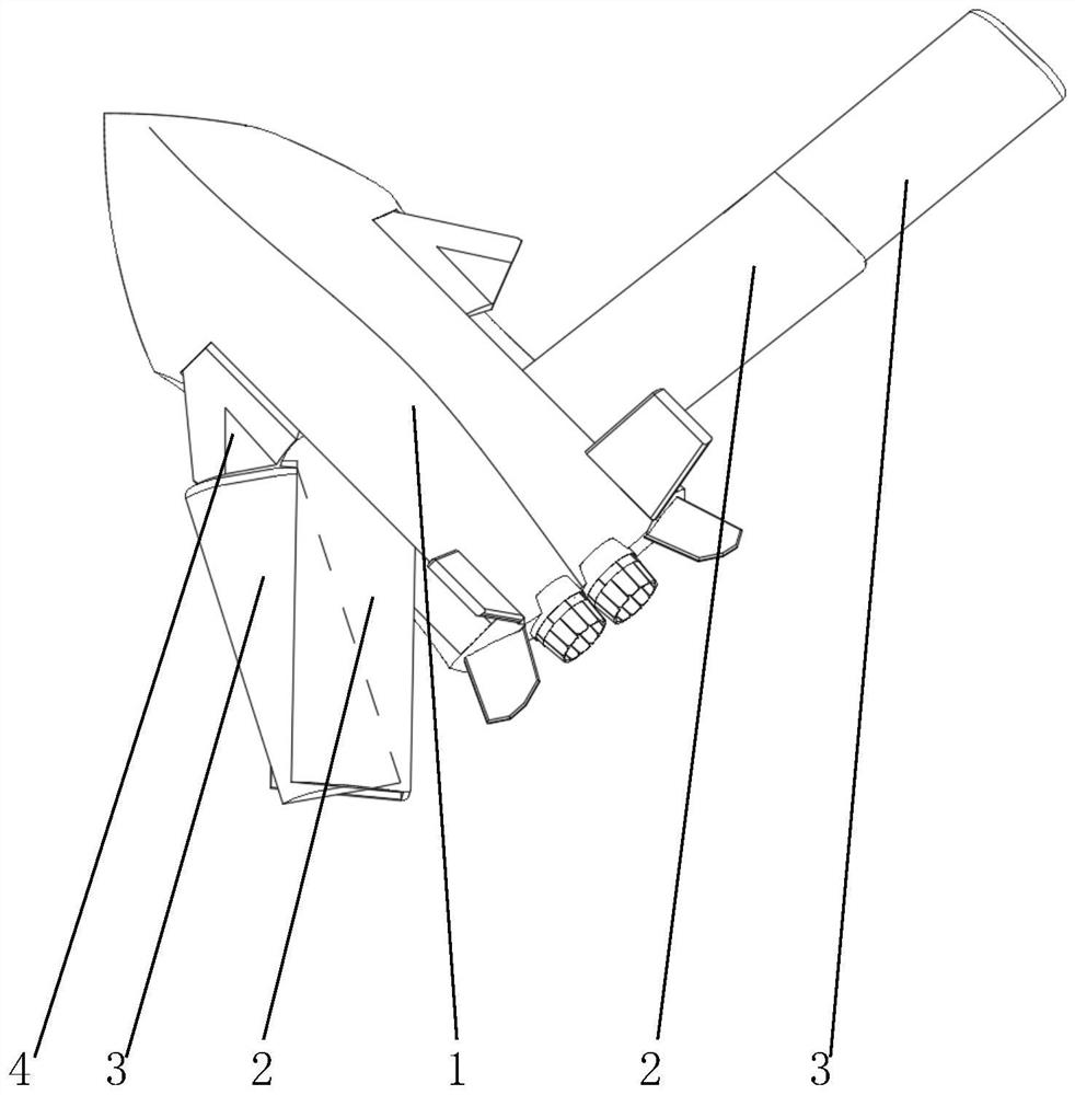
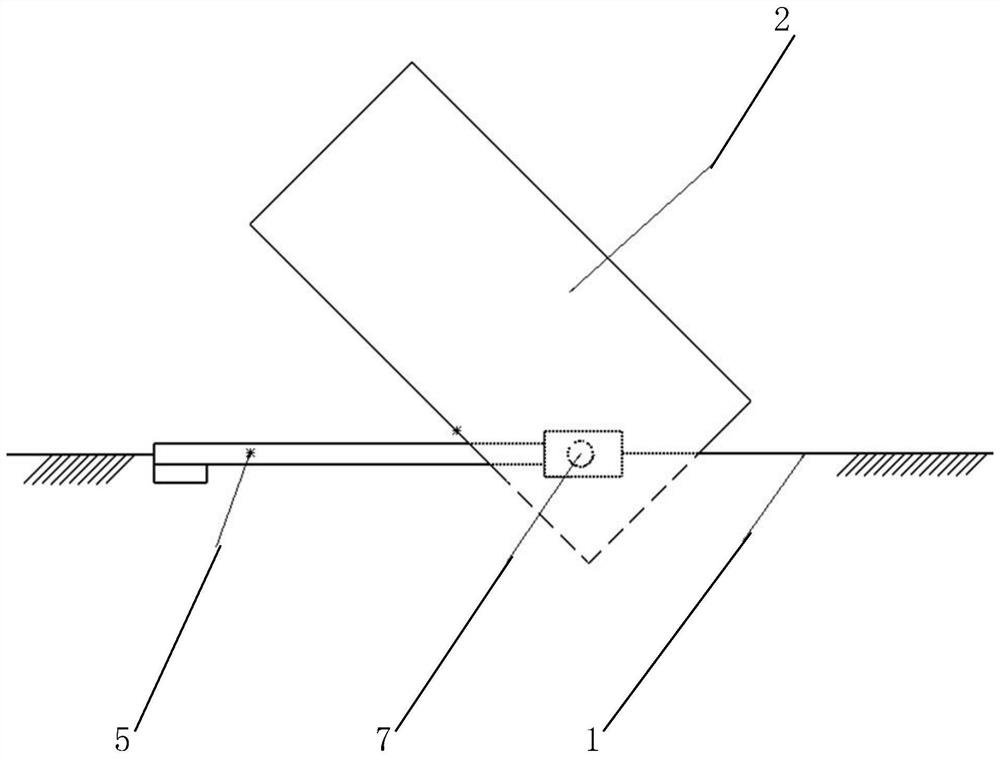
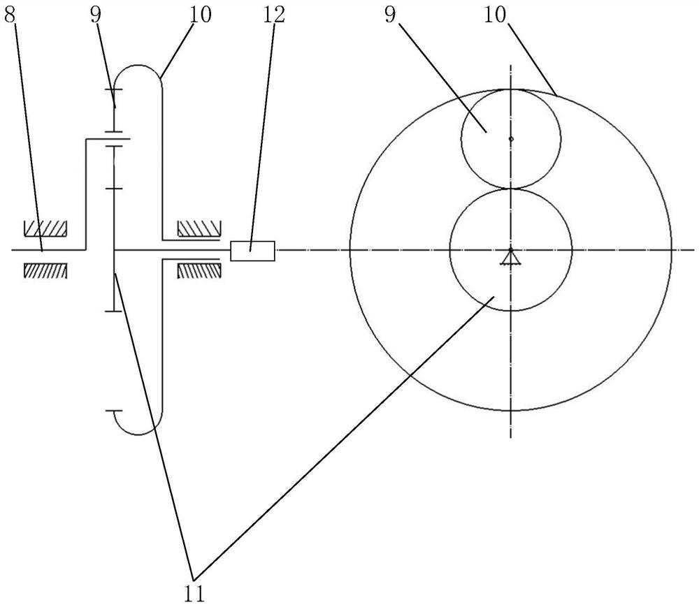
[0042] Attached below Figure 1-7 The present invention is further illustrated with specific examples.

[0043] Such as figure 1 , 5 , Shown in 7, a kind of deformable wing comprises fuselage 1 and two wing parts, and each wing part all comprises:

[0044] The No. 1 wing 2 is movably connected to the side of the fuselage 1, and a first drive rotary joint for driving the No. 1 wing 2 to rotate is configured at the position where the No. 1 wing 2 is movably connected to the side of the fuselage 1;

[0045] The second wing 3 that is rotatably connected to the first wing 2 is configured with a second drive rotary joint for driving the second wing 3 to rotate relative to the first wing 2 at the position where the first wing 2 and the second wing 3 are rotatably connected;

[0046] The aileron 4 that is connected to the side of the fuselage 1 in rotation and is in front of the No. 1 wing 2 and the No. 2 wing 3 is equipped with a first device for driving the aileron 4 to rotate at...


PUM


Abstract

The invention discloses a deformable wing and a deformation method, the deformable wing comprises a fuselage and two wing parts, each wing part comprises: a first wing, which is configured with a first driving rotation joint for driving the first wing to rotate; a second wing, which is provided with a second driving rotating joint for driving the second wing to rotate relative to the first wing; and an aileron, which is provided with a third driving rotating joint for driving the aileron to rotate, wherein in the low-speed flight mode, the ailerons are folded in the fuselage, and the first wing and the second wing are unfolded and form a flight wing structure adaptive to the low-speed flight mode; and, in the high-speed flight mode, the first wing inclines backwards, the second wing rotates and inclines towards the aileron with the second driving rotating joint as the center and is connected with the aileron rotating out of the fuselage, and the first wing, the second wing and the aileron form a flight wing structure suitable for the high-speed flight mode. The unmanned aerial vehicle can flexibly adapt to occasions of high-speed flight and low-speed flight by controlling the deformation state of the wing part.

Description

technical field [0001] The invention relates to the technical field of aircraft, in particular to a deformable wing and a deformation method. Background technique [0002] In recent years, with the continuous improvement of military reconnaissance strikes and real-time monitoring requirements for aircraft performance and the development of technology, advanced aircraft are developing in the direction of multi-tasking. In this case, the traditional fixed wing can no longer meet the application requirements, and the deformed wing that can adapt to various flight tasks and achieve optimal flight performance has attracted increasing attention and research. Today's aircraft usually design the wing as a fixed device, although this can reduce the difficulty of manufacturing the aircraft, but the performance of the aircraft is limited, the purpose is single, and there are many defects. To solve the lift-off problem, a wing with a larger area is required to generate sufficient lift ...

Claims


Application Information

Patent Timeline
IPC IPC(8): B64C3/38
CPCB64C3/38
Inventor 袁家信王宇杨慧李达张恒胡志贤
Owner SHANGHAI UNIV OF ENG SCI
Learn More