
Air conditioner and air supply device thereof

A technology of air supply device and air conditioner, which is applied in the direction of airflow control components, etc., which can solve the inconvenient flexible selection and control of non-circular deflectors and air outlet ducts, uneven distribution of air conditioner air supply devices, and affect user comfort. Effect and other issues, to achieve the effect of improving comfort experience, improving the scope of application, and improving the uniformity of air supply

Active Publication Date: 2015-06-10
HAIER GRP CORP +1
View PDF4 Cites 0 Cited by
  • Summary
  • Abstract
  • Description
  • Claims
  • Application Information

AI Technical Summary

Problems solved by technology

However, since the non-annular deflector and the non-annular air outlet duct are all formed on a non-annular cover body, it is not convenient to flexibly select and control the structure of the non-annular air guide vane and the air outlet duct, and the scope of application is narrow.
Moreover, since the air-conditioning fan blows air from bottom to top, the heat exchange air is not uniform in the circumferential direction when it enters the non-circular air outlet duct, so that the air volume at the lower end of the non-annular air outlet duct is larger, while the air volume at the left and right sides is smaller. , which in turn leads to the uneven distribution of the air sent by the air-conditioning air supply device in the entire circumferential direction, which affects the user's comfort and use effect

Method used


Image

  • Air conditioner and air supply device thereof
  • Air conditioner and air supply device thereof
  • Air conditioner and air supply device thereof

Examples


Embodiment Construction

[0025] The technical solutions of the present invention will be further described in detail below in conjunction with the accompanying drawings and specific embodiments.

[0026] First, a brief description of the technical terms involved in this specific implementation: when referring to the front end or rear end of each structural component, it is defined by the position of the structural component relative to the user under normal use When describing the arrangement position of multiple structural parts before or after, it is also the definition of the position of the device composed of multiple structural parts relative to the user in normal use. The following heat exchange wind refers to the wind from the inside of the air conditioner after heat exchange by the heat exchanger; the non-heat exchange wind refers to the wind from the environment space where the air conditioner is located, which is relative to the heat exchange wind and does not directly come from Part of the ...


PUM


Abstract

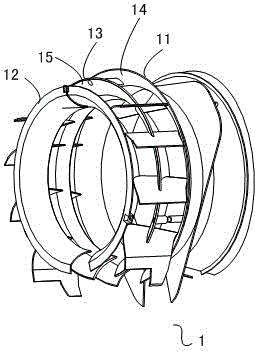
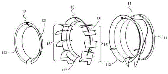
The invention discloses an air conditioner and an air supply device thereof. The air supply device of the air conditioner comprises at least two non-annular air guide assemblies, the middles of the non-annular air guide assemblies are communicated with one another, each non-annular air guide assembly is provided with a front opening and a rear opening and is an individual assembly, the rear opening of each non-annular air guide assembly is used as an air inlet while the front opening of the non-annular air guide assembly is used as an air outlet, the non-annular air guide assemblies are sequentially arrayed in the front-back direction, front-back through air channels are formed in the middles of the non-annular air guide assemblies, a non-annular heat-exchange air channel is formed between each two adjacent non-annular air guide assemblies, the air inlet of the rear-end non-annular air guide assembly is used as a non-heat-exchange air inlet, and the air outlet of the front-end non-annular air guide assembly is used as a mixed air outlet. The air conditioner and the air supply device have the advantages that the air supply device is applied to the air conditioner, so that the quantity of inlet air of the air conditioner can be increased, the softness of outlet air of the air conditioner can be improved, the structure of each non-annular air guide assembly can be conveniently flexibly controlled according to air supply requirements, and the various non-annular air guide assemblies with the different structures can be conveniently machined.

Description

technical field [0001] The invention belongs to the technical field of air conditioning, and in particular relates to an air conditioner and an air conditioner air supply device applied to the air conditioner. Background technique [0002] When the existing vertical air conditioner is blowing air, the wind after heat exchange by the heat exchanger is directly blown out from the air outlet provided on the air conditioner under the action of the internal fan, and all the blown wind is heat exchange air. Generally, no additional air supply device is provided between the heat exchanger and the air outlet. One disadvantage of this kind of air supply air is that all the air sent out is heat exchange air, the air volume is less, and the indoor air circulation speed is slow; another disadvantage is that the air sent out is not soft enough, especially in the cooling mode, the cool wind blown out Blowing directly onto the user makes the user feel uncomfortable. [0003] In order to ...

Claims


Application Information

Patent Timeline
Patent Type & Authority Patents(China)
IPC IPC(8): F24F13/08
Inventor 王永涛刘一辉吕静静韩健
Owner HAIER GRP CORP
Learn More