Connecting assembly with good stability

A technology for connecting components and stability, applied in the field of decoration design, can solve problems such as safety, hidden dangers, falling off, etc., and achieve the effect of fast installation efficiency, high safety, and simple structure

Pending Publication Date: 2021-06-15
ZHEJIANG YASHA DECORATION
View PDF1 Cites 1 Cited by
  • Summary
  • Abstract
  • Description
  • Claims
  • Application Information

AI Technical Summary

Problems solved by technology

[0005] However, the structure of the above-mentioned connecting components still has the following problems: After the decorative panel has been used for a long time, or after it

Method used


Image

  • Connecting assembly with good stability
  • Connecting assembly with good stability
  • Connecting assembly with good stability

Examples


Embodiment 1

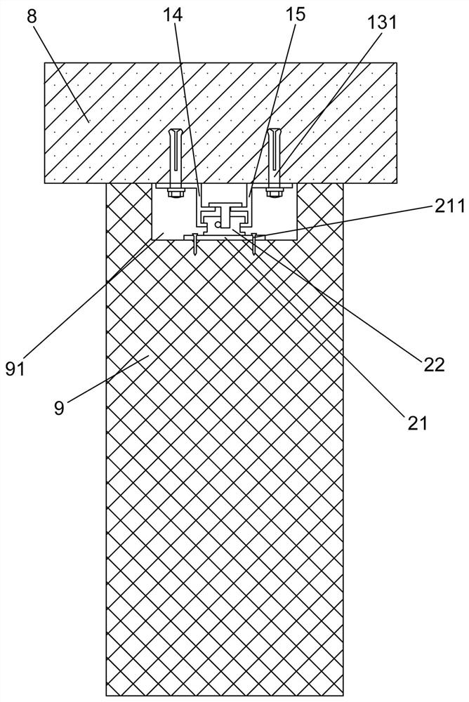
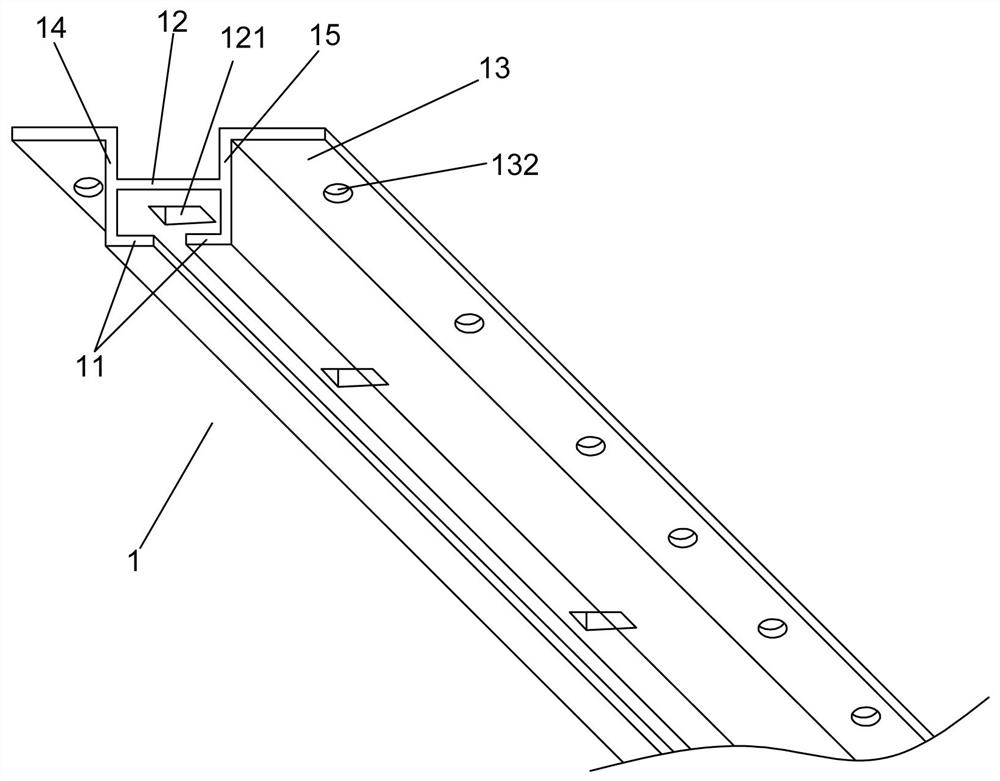
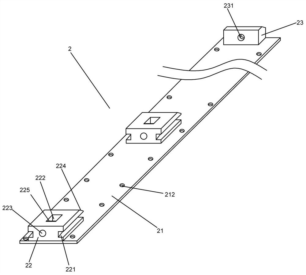
[0033] Example 1: Such as Figure 1 to 6 As shown, only one of the embodiments of the present invention, a good stability connection assembly, including a first connecting member 1 disposed on the fixing plate 8 and one end provided in the forming panel 9 close to the fixing plate 8 The second connector 2 in the groove 91, the second connecting member 2 includes a bottom plate 21 and a card plate 22 disposed to the first connecting member 1 direction, the cardboard 22. The side surface is provided with a slot 221, and the first connector 1 is provided with a raised block 11 extending into the chute 221 adjacent to one end of the bottom plate 21, the width of the chute 221, which is greater than the convex block. The thickness of 11, the first connector 1 is provided with an adjustment plate 12, and the adjustment hole 121 is provided on the adjustment hole 12, and the card plate 22 is provided with a vertically extended square first groove 222 and with The first groove 222 is horiz...

Embodiment 2

[0045] Example 2, still Figure 1 to 6 As shown, only one of the embodiments of the present invention, on the basis of the first embodiment, a stable connection assembly of the present invention, and the first vertical plate 14 and the first, respectively, respectively. The two vertical plate 15, in practice, the adjustment board 12 is disposed between the first vertical plate 14 and the second vertical plate 15 and functions to connect the first vertical plate 14 and the second vertical plate 15, the cardboard 22 is at least A portion of the C-shaped space enclosed in the first vertical plate 14, the adjustment plate 12, and the second vertical plate 15, and slides in the extended direction of the first connector 1 in this space.

[0046] Moreover, the first vertical plate 14 and the second vertical plate 15 are provided with a pad 13 away from one end of the second connecting member 2. The pad 13 is provided with a first bolt 131 for connecting to the fixing plate 8 and a first b...


PUM


Abstract

The invention provides a connecting assembly with good stability, and relates to the technical field of decoration design. The connecting assembly comprises a first connecting piece and a second connecting piece, wherein the second connecting piece comprises a bottom plate and a clamping plate; the side face of the clamping plate is provided with a sliding groove; the first connecting piece is provided with a protruding block; the width of the sliding groove is larger than the thickness of the protruding block; the first connecting piece is provided with an adjusting plate; an adjusting hole is formed in the adjusting plate; a first groove and a second groove are formed in the clamping plate; the second groove communicates with the first groove; a functional plate extending in the direction of the first groove is arranged in the adjusting hole; a functional rod connected with the functional plate is arranged in the second groove; first clamping teeth are arranged on the side edge of the functional plate; and second clamping teeth meshed with the first clamping teeth are arranged on the outer side of the functional rod. According to the invention, the structure is simple, the assembly type installation efficiency is high, the position of a veneer can be adjusted after the veneer is installed, no gap exists between the veneer and a wall body, the stability is good, and the safety is high.

Description

Technical field [0001] The present invention relates to the field of decoration design, [0002] In particular, the present invention relates to a stable connection assembly. Background technique [0003] The current decorative industry is developing towards industrial modular installation. In general, the installation of the forming plate is the universal decorative method in the interior design, which can increase the level of indoor space to beautify the decoration. [0004] Currently, more and more wall-faced hanging plates are used for decoration projects. The use of connectors is also more extensive, but most of the main technologies in China are rivets, bolts, high-strength bolts, electrodes and each Nails. This connection is singlely fixed, so the development of the assembled connection of the panel is increasingly attached, the assembly installation, convenient installation, high safety, China Patent invention patent CN105839884A relates to an adjustable connection assem...

Claims


Application Information

Patent Timeline
IPC IPC(8): E04F13/23
CPCE04F13/0801E04F13/0803E04F13/081
Inventor 何静姿李稳稳王祎娜吴龙楼银松
Owner ZHEJIANG YASHA DECORATION
Why Eureka
Try Eureka