Throat offset type pneumatic thrust vectoring nozzle with orifice jet
A small hole jet and vector nozzle technology, applied in the direction of machines/engines, jet propulsion devices, etc., to achieve the effect of reducing pressure difference resistance
- Summary
- Abstract
- Description
- Claims
- Application Information
AI Technical Summary
Problems solved by technology
Method used
Image
Examples
Embodiment 1
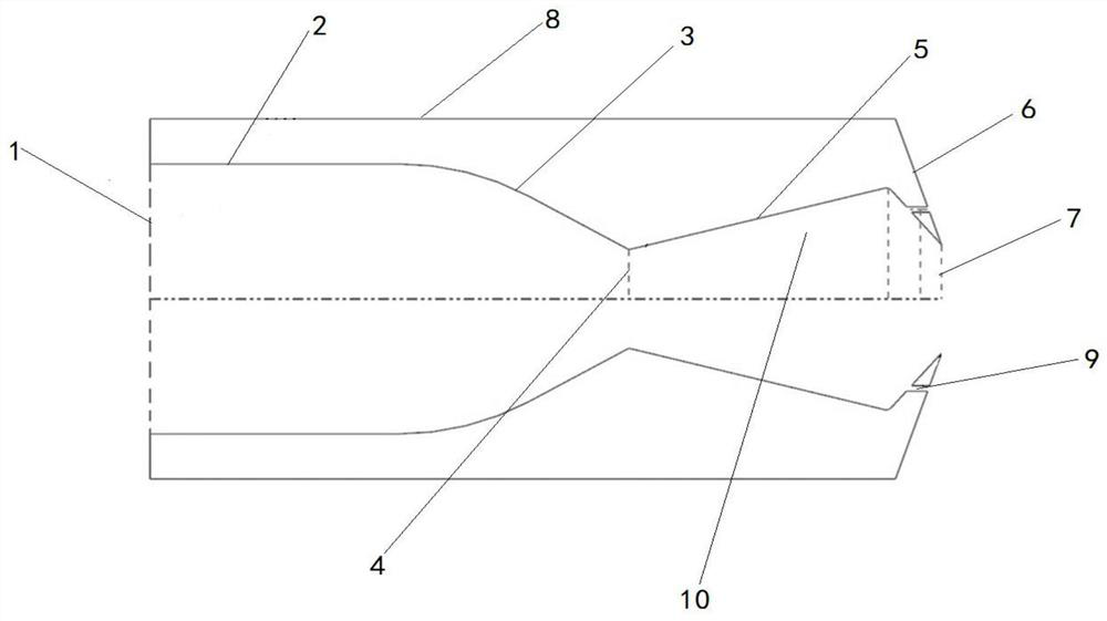
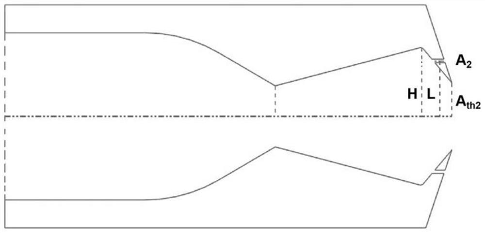
[0037] see figure 1 and figure 2 , this embodiment provides a throat-offset aerodynamic vectoring nozzle of a small-hole jet, including a nozzle body, and the nozzle body includes a nozzle inlet 1, etc. Straight section 2, a converging section 3 at the front of the throat, a throat 4, an expansion section 5 at the front of the second throat, a convergence section 6 at the front of the second throat, and a second throat 7;
[0038] The first throat 4, the expansion section 5 at the front of the second throat, the converging section 6 at the front of the second throat, and the second throat 7 together form the cavity 10, and a jet is provided on the upper part and the lower part of the front convergence section 6 of the second throat Small hole 9, the central axis of the jet small hole 9 is parallel to the central section of the nozzle body, the jet small hole 9 communicates with the cavity 10 and the external recirculation area, and also communicates with the cavity 10 and th...
Embodiment 2
[0048] see Image 6 , Figure 7 , Figure 8 as well as Figure 9 , this embodiment provides a throat-offset type aerodynamic vectoring nozzle of a small-hole jet. The difference between the pneumatic vectoring nozzle provided in this embodiment and the pneumatic vectoring nozzle provided in Embodiment 1 includes: the front converging section of the throat The upper and lower parts of The small hole arrangement scheme can further reduce the area of the low pressure area, increase the average pressure in the low pressure area, and compensate the pressure in the low pressure area more uniformly. The total area A of the orifice at the exit of the small hole 9 2 , still need to meet: 0.1A th2 ≤A 2 ≤0.15A th2 , and the number of jet holes 9 in the upper part is the same as the number of jet holes 9 in the lower part.
[0049] More specifically, in this embodiment, the orifice area of the outlet of each small jet hole 9 is the same.
[0050] Figure 7 is expressed as a ...
Embodiment 3
[0053] see Figure 10 , this embodiment provides a throat-offset type pneumatic vectoring nozzle of small-hole jet. The difference between the pneumatic vectoring nozzle provided in this embodiment and the pneumatic vectoring nozzle in Embodiment 1 is that in this embodiment, it needs to The installation angle θ is limited. The installation angle θ is the angle between the central axis of the jet hole 9 and the central section of the nozzle body. The installation angle θ satisfies: 0≤θ≤30°. The purpose is to change the installation of the jet hole 9 Angle, forming small hole jets with different angles, further improving the flow field structure of the low pressure return area outside the nozzle, and further reducing the resistance.
[0054] To sum up, in the present invention, by setting the small jet holes 9 to connect the cavity of the nozzle with the external recirculation area, the pressure difference between the inner and outer recirculation areas of the concave cavity is...
PUM
 Abstract
Description
Claims
Application Information
 - R&D
- Intellectual Property
- Life Sciences
- Materials
- Tech Scout
- Unparalleled Data Quality
- Higher Quality Content
- 60% Fewer Hallucinations
Browse by: Latest US Patents, China's latest patents, Technical Efficacy Thesaurus, Application Domain, Technology Topic, Popular Technical Reports.
© 2025 PatSnap. All rights reserved.Legal|Privacy policy|Modern Slavery Act Transparency Statement|Sitemap|About US| Contact US: help@patsnap.com


