Eureka AIR delivers breakthrough ideas for toughest innovation challenges, trusted by R&D personnel around the world.

A microblowing structure and method for supercritical airfoil drag reduction and lift increase

A supercritical and airfoil technology, applied in transportation and packaging, affecting the air flow flowing through the surface of the aircraft, and ground installations, etc., can solve the problems that the micro-blowing technology cannot be applied to large passenger aircraft, and the total resistance does not decrease but increases. Achieve the effect of increasing airfoil lift, high drag reduction efficiency and reducing fuel consumption

Active Publication Date: 2020-12-29
BEIHANG UNIV
View PDF5 Cites 1 Cited by
  • Summary
  • Abstract
  • Description
  • Claims
  • Application Information

AI Technical Summary

Problems solved by technology

However, Hwang et al. applied the microblowing technology to the actual symmetrical airfoil in reference [1], which arranged the microporous skin at the chord length position of 11% to 66% of the upper and lower airfoils. The experimental measurement data It shows that under most of Hwang's experimental conditions, the micro-blowing technology causes the total drag to increase instead of decrease when applied to the airfoil
If this defect cannot be overcome, the micro-blowing technology cannot be applied to the actual large passenger aircraft.

Method used


Image

  • A microblowing structure and method for supercritical airfoil drag reduction and lift increase
  • A microblowing structure and method for supercritical airfoil drag reduction and lift increase
  • A microblowing structure and method for supercritical airfoil drag reduction and lift increase

Examples


Embodiment

[0027]Example: NASA-PN2 microporous skin is selected, the micropore diameter is 0.165 mm, the skin thickness is 1.02 mm, and the porosity is 23%. The applied airfoil is RAE2822 airfoil, the incoming flow condition is taken as Mach number is 0.734, and the flight altitude is 10.7km. Skin layout schemes such as Figure 5 As shown, the microblown skin is arranged in the 20% chord length area of ​​the trailing edge of the lower airfoil. The blowing fraction is F=0.008~0.5, and the angle of attack range is α=0°~1°. Table 1 shows the drag reduction and lift-increasing effects of the micro-blowing arranged according to the above scheme at different angles of attack and different blowing fractions, where "w" in the subscript represents the lift or drag value without micro-blowing, C l 、C lw represent the lift coefficient of the airfoil under micro-blowing and without micro-blowing, respectively, and C d 、C dw are the drag coefficients of the airfoil with micro-blowing and withou...


PUM


Abstract

The invention discloses a micro-blowing structure and method for resistance reducing and lift increasing of a supercritical airfoil and belongs to the technical field of aircraft design. Skins with micro holes are arranged near the rear edge of the lower airfoil surface of the airfoil, micro-blowing is started under the cruising state, the wall face friction resistance in the micro-blowing actingarea is reduced remarkably, and the pressure difference resistance of the airfoil is further reduced through increasing of the pressure intensity in a micro-blowing upstream part, so that the total resistance of the airfoil is reduced; meanwhile, the lift of the airfoil can be increased through pressure intensity increasing caused by micro-blowing of the lower airfoil surface; and finally, the resistance reducing and lift increasing effects can be achieved simultaneously. The micro-blowing technique can be used in wide flowing fields including low-speed airliners, high subsonic speed airlinersand even supersonic aircrafts, and rapid development of manufacturing techniques in recent years provides a guarantee for application of the micro-blowing technique.

Description

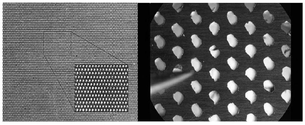
technical field [0001] The invention belongs to the field of aircraft design, and in particular relates to a micro blowing structure and method for supercritical airfoil reducing drag and increasing lift. Background technique [0002] Micro-Blowing Technique (MBT) is a low-energy drag control technology developed to reduce the frictional resistance of the turbulent boundary layer on the surface of large passenger aircraft. This technology was proposed by Hwang of NASA Glenn Research Center in 1994. The microblowing technology opens a large number of micropores on the wall (such as figure 1 The typical microporous wall plate shown in ) blows air into the turbulent boundary layer near the wall through these micropores, so as to reduce the frictional resistance of the wall. The micro-blowing technology retains the drag reduction mechanism of the traditional air-blowing drag reduction technology for surface frictional resistance, and the frictional resistance of the microporous...

Claims


Application Information

Patent Timeline
Patent Type & Authority Patents(China)
IPC IPC(8): B64C21/04B64F5/00
CPCB64C21/04B64F5/00
Inventor 高振勋蒋崇文李椿萱张智超
Owner BEIHANG UNIV
Why Eureka
Eureka Blog
Learn More