A Mechanical Seal Structure Suitable for Fuel Cooling Turbine

A technology of mechanical sealing and cooling turbine, applied in the direction of engine sealing, gas turbine device, mechanical equipment, etc., can solve the problems of seal failure, rubber ring failure, poor sealing effect, etc., to reduce the degree of runout, good sealing effect, working temperature low effect

Active Publication Date: 2021-11-26
BEIHANG UNIV
View PDF7 Cites 0 Cited by
  • Summary
  • Abstract
  • Description
  • Claims
  • Application Information

AI Technical Summary

Problems solved by technology

The intrusion of stagnant high-temperature air brought about by hypersonic speed will cause the turbine rotor disc cavity to be in a high-temperature environment, which will easily cause the conventional mechanical seal auxiliary sealing element - the O-ring rubber ring to fail, and eventually lead to poor sealing effect or even seal damage. Serious consequences

Method used


Image

  • A Mechanical Seal Structure Suitable for Fuel Cooling Turbine

Examples


Embodiment Construction

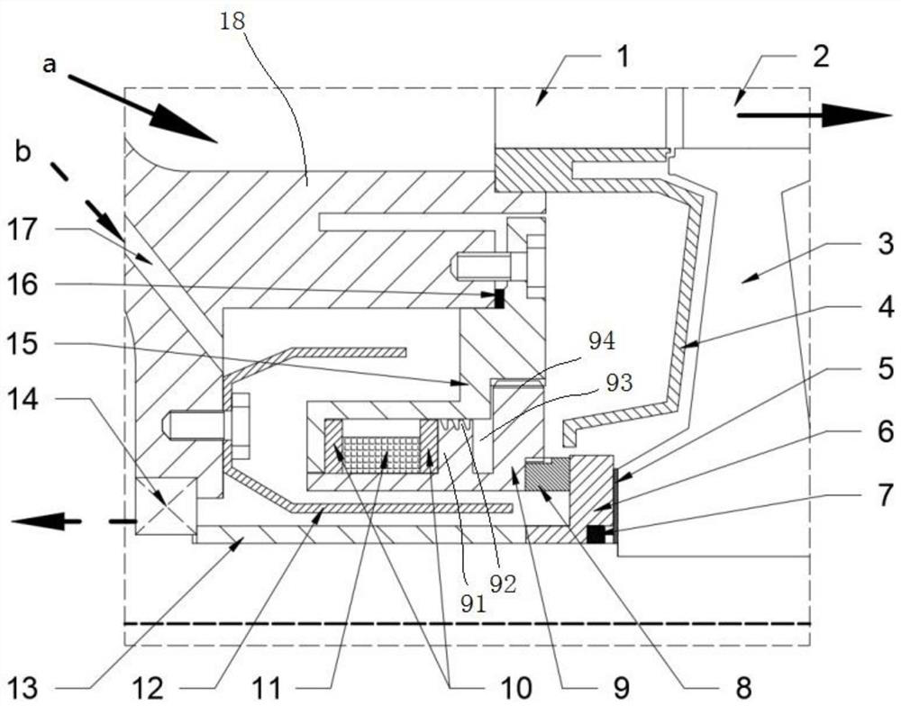
[0033] figure 1 It is a schematic main cross-sectional view of a mechanical seal structure suitable for a fuel-cooled turbine according to an embodiment of the present application, wherein a is the flow direction of the mainstream gas working medium, and b is the cooling oil flow inlet and outlet. This embodiment provides a mechanical seal structure suitable for fuel-cooled turbines, wherein the turbine includes a stationary casing 18, a bearing 14 and a sleeve 13 sleeved in the stationary casing 18, and a The turbine guide vane 1, the turbine rotor blade 2, the turbine disk 3 and the disk chamber baffle plate 4 in the casing 18. The sleeve 13 is in contact with the inner ring of the bearing 14 . The upper end of the disk cavity baffle plate 4 is connected to the base of the turbine guide vane 1, and plays a role in blocking the leakage of hot gas in the rotating and static gap in the turbine disk cavity, which can not only play the role of heat insulation, protect the sealin...


PUM


Abstract

The application discloses a mechanical seal structure suitable for fuel cooling turbines, and relates to the field of mechanical seals. It is used for the oil-air seal between the rotary and static systems of the oil-immersed cooling bearing structure under the condition of high temperature and high speed, and solves the problem of high temperature in the working environment of the bearing. It includes a fixed base, a movable support, a rubber spring, a static friction ring, a dynamic friction ring and a baffle. The fuel oil for cooling is injected into the bearing cavity through the oil delivery pipe, and flows around the baffle plate to enhance the flow and heat exchange in the internal cavity area of ​​the friction dynamic and static rings. It flows into the bearing ring cavity along the interlayer between the sleeve and the baffle, and finally flows out of the bearing cavity. The rubber spring component is used in the mechanical seal structure, which can not only achieve a good sealing effect, but also provide the axial force required for the pre-tightening of the frictional static and dynamic rings by pressing and fitting with the end wall. Therefore, the mechanical seal structure has the characteristics of high working temperature and speed limit, good cooling and heat exchange effect, low bearing working temperature, and simple and reliable structure.

Description

technical field [0001] The present application relates to the field of mechanical seals, in particular to a mechanical seal structure with a rubber spring and a simple structure suitable for high-temperature and high-speed fuel cooling turbines. Background technique [0002] The mechanical seal, that is, the end face seal, is an axial end face sealing device that uses the elastic force preload of the elastic element and the pressure difference of the medium to compress the end face of the moving ring and the end face of the static ring to achieve the sealing effect. It relies on the relative sliding friction of the closely fitted dynamic and static ring end faces and auxiliary sealing elements to prevent the leakage of media on both sides. As an indispensable key component in fluid machinery and power machinery, the performance of mechanical seals determines the vital parameters of the machine such as safety, reliability, durability, and efficiency. [0003] For power gener...

Claims


Application Information

Patent Timeline
Patent Type & Authority Patents(China)
IPC IPC(8): F16J15/34F02C7/28
CPCF02C7/28F16J15/3404F16J15/3452
Inventor 徐国强赵广龙董苯思闻洁孙京川
Owner BEIHANG UNIV
Why Eureka
Try Eureka