
Rotor assembly and self-starting permanent magnet synchronous reluctance motor

A technology of rotors and components, which is applied to synchronous machine parts, motors, electric components, etc., can solve the problems of limiting the permanent magnet torque and efficiency of the motor, so as to increase the amount of use, increase the placement space, and improve the efficiency of the motor Effect

Active Publication Date: 2022-05-17
GREE ELECTRIC APPLIANCES INC
View PDF0 Cites 0 Cited by
  • Summary
  • Abstract
  • Description
  • Claims
  • Application Information

AI Technical Summary

Problems solved by technology

[0003] However, the rotor of the self-starting permanent magnet assisted synchronous reluctance motor is equipped with filling slots and permanent magnets at the same time, and the areas of the two are mutually restricted, which limits the improvement of the permanent magnet torque and efficiency of the motor.

Method used


Image

  • Rotor assembly and self-starting permanent magnet synchronous reluctance motor
  • Rotor assembly and self-starting permanent magnet synchronous reluctance motor
  • Rotor assembly and self-starting permanent magnet synchronous reluctance motor

Examples


Embodiment Construction

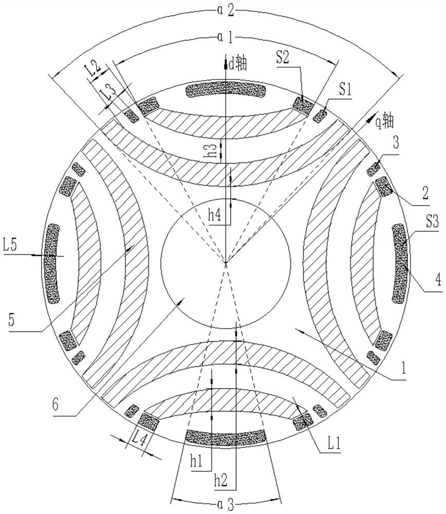
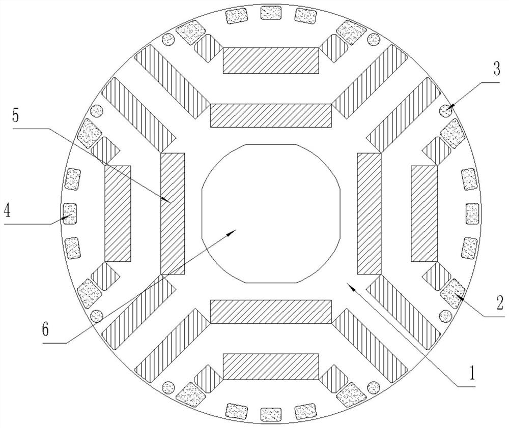
[0031] see in conjunction Figure 1 to Figure 4 As shown, according to the embodiment of the present application, the rotor assembly includes a rotor core 1, and the cross section of the rotor core 1 is provided with a shaft hole 6, a mounting groove, a first filling groove 2 and a dislocation filling groove 3, and the mounting groove is provided with There are permanent magnets 5, and there are at least two layers of permanent magnets 5 arranged along the d-axis direction. The permanent magnets 5 located at the radially innermost side along the d-axis direction extend to the rotor outer circle of the rotor core 1. The first filling groove 2 is arranged along the d-axis direction. The d-axis direction is located at both ends of the radially outermost permanent magnet 5, and the dislocation filling groove 3 is arranged at both ends of the magnetic conduction channel between adjacent permanent magnets 5, and is located between the first filling groove 2 and the permanent magnet 5...


PUM


Abstract

The present application provides a rotor assembly and a self-starting permanent magnet synchronous reluctance motor. The rotor assembly includes a rotor core (1). The cross section of the rotor core (1) is provided with a shaft hole (6), a mounting groove, a first filling groove (2) and a dislocation filling groove (3). Permanent magnets (5) are provided, and the permanent magnets (5) are arranged in at least two layers along the d-axis direction, and the permanent magnets (5) that are radially innermost along the d-axis direction extend to the rotor outer circle of the rotor core (1) , the first filling groove (2) is arranged at both ends of the permanent magnet (5) located at the outermost radial direction along the d-axis direction, and the dislocation filling groove (3) is arranged in the magnetic conduction between adjacent permanent magnets (5) Both ends of the channel are located between the first filling groove (2) and the permanent magnet (5). According to the rotor assembly of the present application, the structure of the filling slot and the permanent magnet can be allocated reasonably, the space for placing the permanent magnet can be increased, and the permanent magnet torque and efficiency of the motor can be improved.

Description

technical field [0001] The present application relates to the technical field of motors, in particular to a rotor assembly and a self-starting permanent magnet synchronous reluctance motor. Background technique [0002] Self-starting permanent magnet assisted synchronous reluctance motor combines the advantages of asynchronous motor on the basis of permanent magnet assisted synchronous reluctance motor. torque to achieve constant speed operation. Compared with the asynchronous motor, the motor can run at a constant speed with low rotor loss and high efficiency; compared with the asynchronous start permanent magnet synchronous motor, the permanent magnet consumption is small and the motor cost is low. [0003] However, the rotor of the self-starting permanent magnet assisted synchronous reluctance motor is equipped with filling slots and permanent magnets at the same time, and the areas of the two are mutually restricted, which limits the improvement of the permanent magnet ...

Claims


Application Information

Patent Timeline
Patent Type & Authority Patents(China)
IPC IPC(8): H02K1/27H02K1/272H02K21/02
CPCH02K1/27H02K1/272H02K21/02Y02T10/64
Inventor 李霞肖勇张志东史进飞
Owner GREE ELECTRIC APPLIANCES INC
Learn More