
Wool separating and feeding device

A wool and driving device technology, applied in the field of wool separation and feeding device, can solve the problems of low production efficiency, low quality, increased cost, etc., and achieve the effect of improving wool separation and feeding efficiency

Pending Publication Date: 2021-06-18
漳州恒誉自动化科技有限公司
View PDF0 Cites 0 Cited by
  • Summary
  • Abstract
  • Description
  • Claims
  • Application Information

AI Technical Summary

Problems solved by technology

For the hair of the brush head of the brush, the traditional method adopts the method of artificial hair, but the artificially produced brush head not only has more or less hair, but also has different thickness, low quality, and low production efficiency, especially In today's rising labor costs, such a production method that consumes human resources has increased a lot of costs for companies producing such products, and it does not meet the needs of the current era.

Method used


Image

  • Wool separating and feeding device
  • Wool separating and feeding device
  • Wool separating and feeding device

Examples


no. 1 example

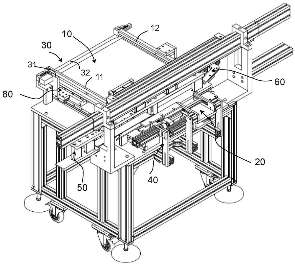
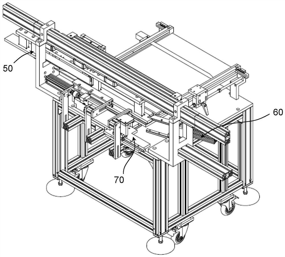
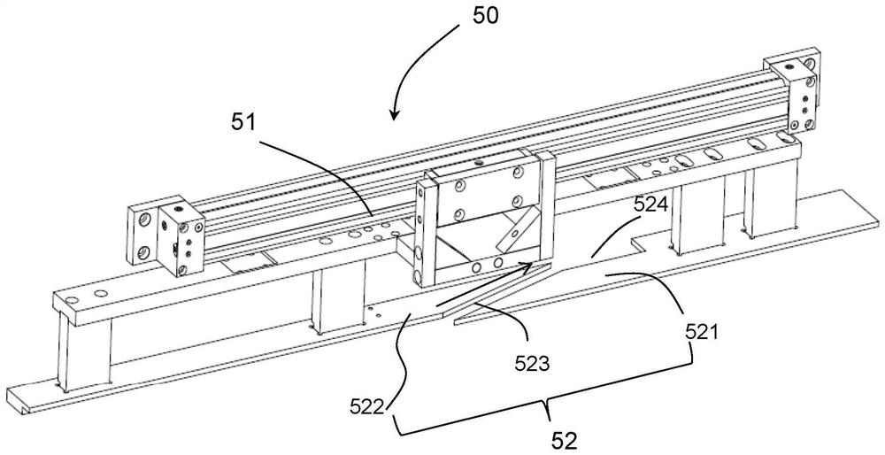
[0059] Please refer to figure 1 , figure 2 As shown, the wool separating and feeding device provided in this embodiment includes a machine platform, a wool loading hopper 10 , a feeding chute 20 , a pressing device 30 , a wool separating device 50 , a wool pushing device 60 and a wool feeding device 70 .

[0060] in:

[0061] The machine platform 10 is formed with a wool storage and storage station, a wool dividing and gathering station and a wool feeding station arranged in sequence along the longitudinal direction.

[0062] Loading wool hopper 10 is arranged at the wool storage and release station place, and the end of wool loading hopper 10 toward the wool dividing and gathering station is the wool loading hopper discharge end, and wool is stored upright in the wool loading hopper 10.

[0063] Feeding chute 20 is arranged at the wool feeding station place, and feeding chute 20 extends along the longitudinal direction, and one end of feeding chute 20 near the wool dividin...

no. 2 example

[0102] The functions realized by the key components included in the wool dividing and feeding device provided in this embodiment are basically the same as those in the first embodiment, so when understanding the structure and working process of the wool dividing and feeding device in this embodiment , reference may be made to the relevant description in the first embodiment and the corresponding accompanying drawings.

[0103] The wool separating and feeding device provided in this embodiment includes a wool loading hopper, a feeding trough, a pressing device, a wool separating device, a wool pushing device and a wool feeding device, wherein:

[0104] The fur loading hopper is used for storing wool, and has a feeding end of the wool loading hopper.

[0105] The feeding chute is used for storing wool from the wool loading hopper, and has a feeding end of the feeding chute.

[0106] The wool separating device is arranged near the discharge end of the wool loading hopper, and it...


PUM


Abstract

The invention provides a wool separating and feeding device. The wool separating and feeding device comprises a machine table, and a wool loading hopper, a feeding groove, a wool pressing device, a wool separating device, a wool pushing device and a wool conveying device which are arranged on the machine table, wherein the wool pressing device is used for pressing wool in the wool loading hopper to the feeding groove, the wool separating device and the wool pushing device are used for cutting off the wool from the wool in the wool loading hopper and collecting the cut wool to the feeding end of the feeding groove, and the wool conveying device is used for conveying the wool collected to the feeding end of the feeding groove into the feeding groove. According to the wool separating and feeding device, automatic wool separating of the wool can be achieved, the separated wool is loaded into the feeding groove, and therefore automatic feeding is achieved. Compared with the prior art, the wool separating and feeding efficiency can be remarkably improved.

Description

technical field [0001] The invention relates to the field of brush production, in particular to a wool separating and feeding device. Background technique [0002] Brushes such as paint brushes are widely used in daily life. For the hair of the brush head of the brush, the traditional method adopts the method of manual hair loading, but the artificially produced brush head not only has more or less hair, but also has different thickness, low quality, and low production efficiency, especially In today's rising labor costs, such a production method that consumes human resources has increased a lot of costs for companies producing such products, and it does not meet the needs of the current era. [0003] In order to replace the manual wool-loading method, the applicant has invested a large amount of research and development resources in the development of an automatic wool-loading machine. The automatic loading of the brush head needs to complete at least the following proces...

Claims


Application Information

Patent Timeline
IPC IPC(8): A46D3/08
CPCA46D3/08A46D3/082
Inventor 林锋传
Owner 漳州恒誉自动化科技有限公司
Learn More