A printed circuit board edge automatic film sticking device

A printed circuit board and film sticking device technology, which is applied in the field of automatic film sticking devices on the edge of printed circuit boards, can solve the problems of low automation, low work efficiency, uniformity, etc., and achieve less manual participation, controllable sticking width, The effect of improving productivity

Active Publication Date: 2021-07-20
四川英创力电子科技股份有限公司
View PDF7 Cites 0 Cited by
  • Summary
  • Abstract
  • Description
  • Claims
  • Application Information

AI Technical Summary

Problems solved by technology

In the prior art, the circuit board is usually fixed on the rotating device, the circuit board is rotated, and then the protective film is manually wrapped around the circuit board. The degree of automation is low, the work efficiency is not high, and the protective film on the upper and lower sides of the circuit board cannot be guaranteed. The width is uniform and uniform. If the protective film is too wide, it is easy to cover the wiring pattern on the circuit board. If the protective film is too narrow, the protective effect will be reduced.

Method used


Image

  • A printed circuit board edge automatic film sticking device
  • A printed circuit board edge automatic film sticking device
  • A printed circuit board edge automatic film sticking device

Examples


specific Embodiment approach

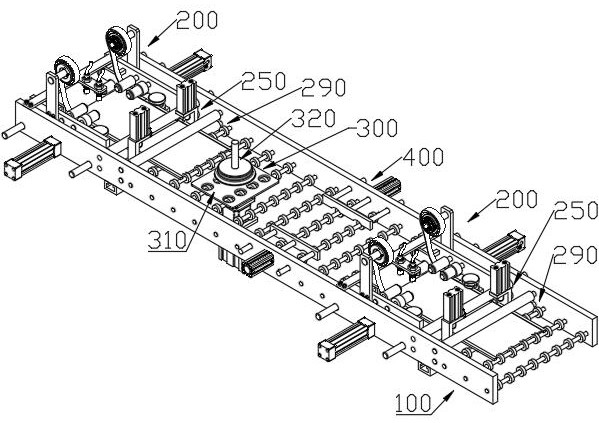
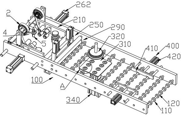
[0063] Put the circuit board 1 from the first group of film sticking mechanism 200 at the front end of the conveying track 100, before pasting the protective film 3 on the first circuit board 1, first pull out the protective film 3 on both sides from the protective film coil 2, Make the front end of the protective film 3 pass between the cylindrical rollers 221, and then start to put the circuit board 1 in, and the circuit board 1 can be fed in by conveying line transmission to improve efficiency. When the circuit board 1 enters between the cylindrical rollers 221, the protective film 3 starts to contact the top surface of the circuit board 1. After the circuit board 1 passes through the cylindrical rollers 221, the protective film 3 on the top surface has been bonded to the surface of the circuit board 1. , along with the movement of the circuit board 1, the protective film 3 is also slowly pulled out, and then the circuit board 1 passes through the bending roller 230 and the ...


PUM


Abstract

An automatic film-attaching device for the edge of a printed circuit board comprises two sets of film-attaching mechanisms, and a rotating plate mechanism and a positioning mechanism are arranged between the film-attaching mechanisms. The film sticking mechanism includes rolling components arranged on both sides of the circuit board. The rolling component is provided with a protective film roll material. The rolling component is equipped with a flattening roller group, a bending roller and a shaping wheel in turn. The protective film is passed through the flattening roller group, Bending rollers and shaping wheels are gradually pasted to the top and bottom of the circuit board. There is a cutting mechanism behind the rolling assembly, with a cutter and a cutter seat. The cutter is arranged above the protective film on both sides of the circuit board, and the cutter seat is arranged below the protective film. The cutter and the cutter seat cooperate to The protective film is cut off. The rotating plate mechanism includes a rotating plate and a pressing cover for rotating the circuit board. The positioning mechanism includes side push plates arranged on both sides of the conveying track, and the sliding direction of the side push plates is horizontal and perpendicular to the conveying direction of the circuit board. The protective film can be automatically attached to the four sides of the circuit board with high efficiency, and the pasting width of the protective film on the upper and lower sides of the circuit board can be controlled.

Description

technical field [0001] The invention belongs to the technical field of printed circuit board production, in particular to an automatic film sticking device for the edge of a printed circuit board. Background technique [0002] In the production process of the printed circuit board, in order to protect the four sides of the printed circuit board and prevent damage and scratches, etc., a protective film is usually pasted around the circuit board so that the protective film covers the sides and top surface of the circuit board. The part of the bottom near the edge. In the prior art, the circuit board is usually fixed on the rotating device, the circuit board is rotated, and then the protective film is manually wrapped around the circuit board. The degree of automation is low, the work efficiency is not high, and the protective film on the upper and lower sides of the circuit board cannot be guaranteed. The width is uniform. If the protective film is too wide, it is easy to cov...

Claims


Application Information

Patent Timeline
Patent Type & Authority Patents(China)
IPC IPC(8): B65B33/02B65B61/06
CPCB65B33/02B65B61/06
Inventor 李清华牟玉贵张仁军杨海军邓岚
Owner 四川英创力电子科技股份有限公司
Why Eureka
Try Eureka