
Convenient and rapid supporting pile for steel plate group laying

A kind of support pile, convenient technology, applied in the direction of sheet pile wall, building, foundation structure engineering, etc., can solve the problems of left and right shaking, wear of positioning rod, unstable support, etc., and achieve the effect of smooth downward movement and not easy to tilt

Inactive Publication Date: 2021-06-18
郎斌斌
View PDF0 Cites 0 Cited by
  • Summary
  • Abstract
  • Description
  • Claims
  • Application Information

AI Technical Summary

Problems solved by technology

[0003] The existing portable support piles for laying steel plate groups have the problems of easy left and right shaking and unstable support after the pillars are inserted into the ground, which brings inconvenience to actual operation; the existing portable support piles for laying steel plate groups have the problem of positioning The rods wear out after long-term use, and cannot be replaced conveniently and quickly, which brings inconvenience to the actual operation. For this reason, the present invention proposes a portable support pile for laying steel plate groups to solve the above problems

Method used


Image

  • Convenient and rapid supporting pile for steel plate group laying
  • Convenient and rapid supporting pile for steel plate group laying
  • Convenient and rapid supporting pile for steel plate group laying

Examples


Embodiment Construction

[0023] The following will clearly and completely describe the technical solutions in the embodiments of the present invention with reference to the accompanying drawings in the embodiments of the present invention. Obviously, the described embodiments are only some, not all, embodiments of the present invention. Based on the embodiments of the present invention, all other embodiments obtained by persons of ordinary skill in the art without making creative efforts belong to the protection scope of the present invention.

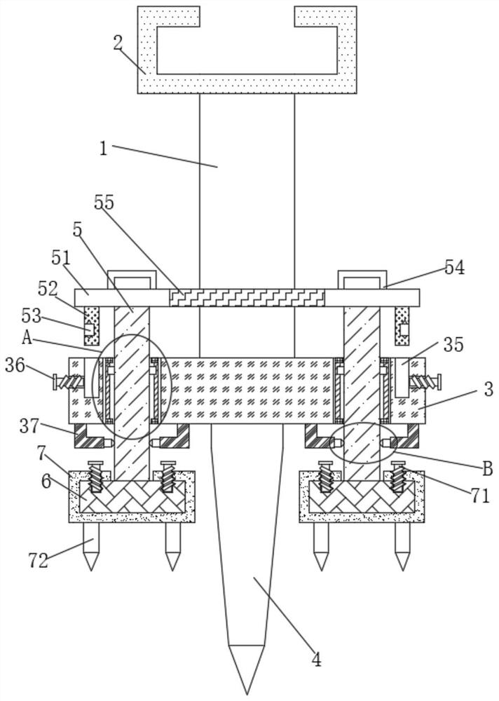
[0024] see Figure 1 to Figure 4 , the present invention provides a technical solution: a portable support pile for laying steel plate groups, including a pillar 1, a support plate 2 is fixedly installed on the top of the pillar 1, a bottom plate 3 is fixedly installed on the bottom end of the pillar 1, and the bottom of the bottom plate 3 The positioning column 4 is fixedly installed at the position close to the middle of the end;

[0025] The inside of the ...


PUM


Abstract

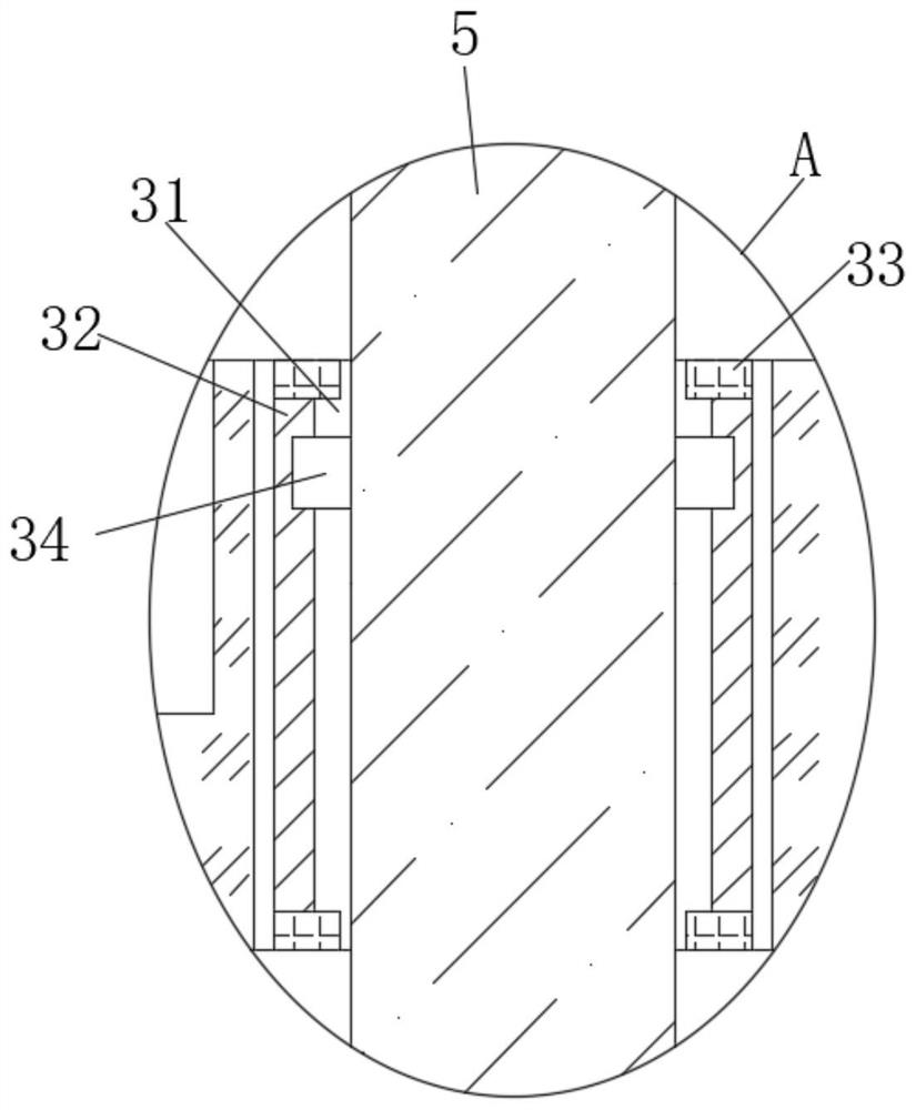
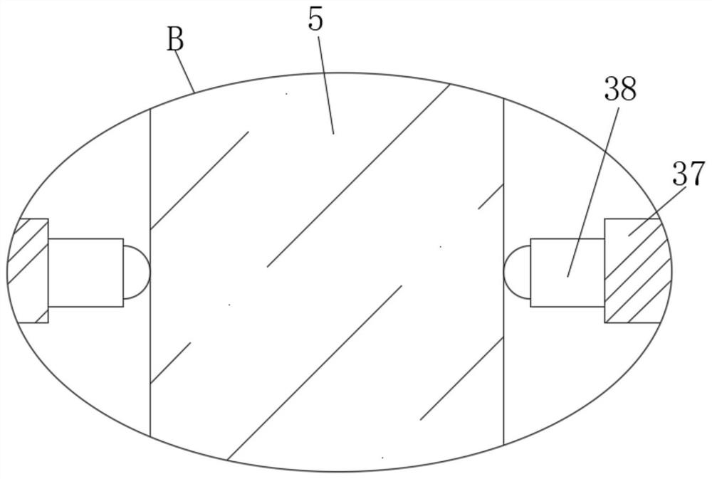
The invention relates to the technical field of supporting piles, in particular to a convenient and rapid supporting pile for steel plate group laying. The pile comprises a supporting column, a supporting disc is fixedly mounted at the top end of the supporting column, a bottom plate is fixedly mounted at the bottom end of the supporting column, a positioning column is fixedly mounted at the position, close to the middle, of the bottom end of the bottom plate, and movable grooves are formed in the positions, close to the two sides, in the bottom plate; sliding rails are fixedly mounted on the inner walls of the two sides of the two movable grooves, limiting blocks are fixedly mounted at the two ends of the four sliding rails, sliding blocks are slidably connected to the outer surfaces of the four sliding rails, the outer surfaces of one sides of the four sliding blocks are fixed to the outer surfaces of the corresponding sides of corresponding movable rods, fixing grooves are formed in the positions, close to the two sides, of the top end of the bottom plate, and fixing bolts are movably connected to the two sides of the bottom plate through threads. By arranging four positioning rods, on one hand, the ground can be further positioned and fixed, on the other hand, the bottom plate and the supporting column can be supported from left and right, and thus left-right inclination of the bottom plate and the supporting column can be prevented to a certain extent.

Description

technical field [0001] The invention relates to the technical field of support piles, in particular to a portable support pile for laying steel plate groups. Background technique [0002] Support piles are piles that are used in engineering and ultimately act as forces in buildings and structures. Engineering piles are piles used on engineering entities, which must bear certain loads. During the laying of the steel plate group, a special support pile is required for support. However, there are many problems in this support pile in actual use. . [0003] The existing portable support piles for laying steel plate groups have the problems of easy left and right shaking and unstable support after the pillars are inserted into the ground, which brings inconvenience to actual operation; the existing portable support piles for laying steel plate groups have the problem of positioning The rods wear out after long-term use and cannot be replaced conveniently and quickly, which brin...

Claims


Application Information

Patent Timeline
Patent Type & Authority Applications(China)
IPC IPC(8): E02D5/24
CPCE02D5/24
Inventor 郎斌斌
Owner 郎斌斌
Learn More