A wellhead quick thawing device

A fast, hole-mounting technology, which is applied in isolation devices, wellbore/well components, earthwork drilling and production, etc., can solve the problems of long preparation time of steam truck equipment, high cost of steam truck use, and use of steam trucks, etc., to improve the use of steam trucks Practicality and convenience, increase energy utilization, increase the effect of defrosting speed

Active Publication Date: 2021-10-19
DAQING TIANDEZHONG PETROLEUM SCI & TECH CO LTD
View PDF10 Cites 0 Cited by
  • Summary
  • Abstract
  • Description
  • Claims
  • Application Information

AI Technical Summary

Problems solved by technology

[0002] Due to seasonal reasons in northern oilfields, for some oil wellhead water-mixed pipelines and water wellhead pipelines, blockages often occur in winter due to internal freezing. The liquid in the pipeline stops flowing, causing a large area of ​​the entire pipeline to freeze, causing oil and gas wells or water wells to stop production. The method can only be used when the freezing of the pipeline is not serious. This method is not only inefficient, but also has potential safety hazards during the operation, and it is easy to burn the operator
[0003] In winter in the northern region, pipelines are often frozen and blocked during construction operations, but open flames are strictly prohibited on the oil well site. The common practice on site is to use steam trucks to unblock pipelines with high-temperature steam, but this method has disadvantages: 1. Steam The use of automobiles is expensive, and steam vehicles are frequently used; 2. The steam vehicle equipment takes a long time to prepare, which seriously reduces the work efficiency on site. It often takes a long time to dredge a well, and there are many wells, and the operation is time-consuming and laborious. At the same time, the staff spends a long time Working in a low temperature and windy environment can easily cause frostbite and bring great trouble to the work

Method used


Image

  • A wellhead quick thawing device
  • A wellhead quick thawing device
  • A wellhead quick thawing device

Examples


Embodiment Construction

[0023] The following will clearly and completely describe the technical solutions in the embodiments of the present invention with reference to the accompanying drawings in the embodiments of the present invention. Obviously, the described embodiments are only some, not all, embodiments of the present invention. Based on the embodiments of the present invention, all other embodiments obtained by persons of ordinary skill in the art without making creative efforts belong to the protection scope of the present invention.

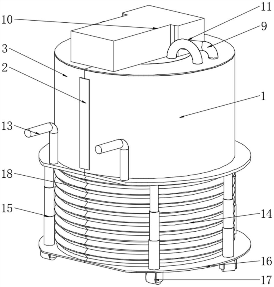
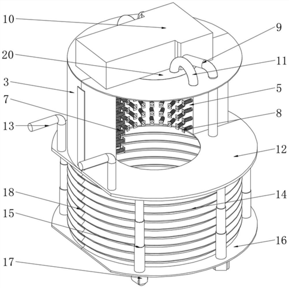
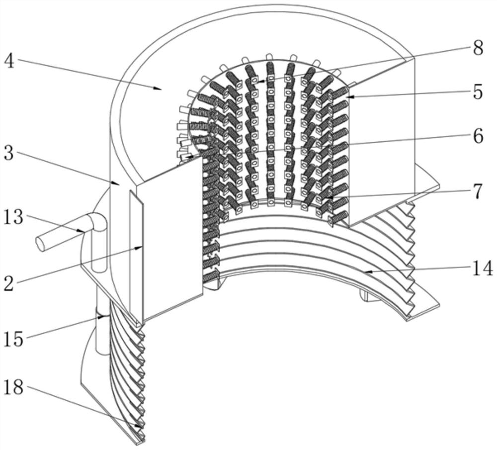
[0024] see Figure 1-5 , a wellhead rapid thawing device, comprising a right cover 1, a left cover 3 is movably installed on one side of the right cover 1, and a support plate 12 is fixedly installed on the bottom of the right cover 1 and the left cover 3, and the support plate The upper end of 12 is fixedly equipped with handrail 13, and the bottom of support plate 12 is fixedly equipped with thermal curtain 14, and the middle part of support plate 12 and the...


PUM


Abstract

The invention relates to the technical field of wellhead thawing devices, and discloses a wellhead quick thawing device, which includes a right cover, a left cover is movably installed on one side of the right cover, and the connection between the right cover and the left cover Both are fixedly connected with first hinges, the inside of the right cover and the left cover are fixedly installed with a partition, the middle part of the partition is provided with a mounting hole, and the other side of the mounting hole is provided with a cavity , the inside of the installation hole is movably installed with a nozzle, the front end of the nozzle is fixedly installed with an extruding plate, the outside of the nozzle is sleeved with a spring, and the inside of the cavity is movably installed with an air supply pipe. The wellhead rapid thawing device is convenient to use by setting the device in a left and right opening and closing shape, and connecting it through the first hinge, and wrapping the device completely outside the wellhead device for a week, which is convenient for simultaneous heating and thawing of the wellhead device. Increase the defrosting speed of the device, which is convenient for the operator to use.

Description

technical field [0001] The invention relates to the technical field of wellhead thawing devices, in particular to a wellhead quick thawing device. Background technique [0002] Due to seasonal reasons in northern oilfields, for some oil wellhead water-mixed pipelines and water wellhead pipelines, blockages often occur in winter due to internal freezing. The liquid in the pipeline stops flowing, causing a large area of ​​the entire pipeline to freeze, causing oil and gas wells or water wells to stop production. The method can only be used when the freezing of the pipeline is not serious. This method is not only inefficient, but also has potential safety hazards during the operation, and it is easy to burn the operator. [0003] In winter in the northern region, pipelines are often frozen and blocked during construction operations, but open flames are strictly prohibited on the oil well site. The common practice on site is to use steam trucks to unblock pipelines with high-te...

Claims


Application Information

Patent Timeline
Patent Type & Authority Patents(China)
IPC IPC(8): E21B36/00
CPCE21B36/00
Inventor 张淞源张虎
Owner DAQING TIANDEZHONG PETROLEUM SCI & TECH CO LTD
Why Eureka
Try Eureka