Electrical embedded pipe protection device and construction method thereof

A technology for electrical pre-embedded pipes and protective devices, which is applied in the direction of cable installation devices, electrical components, and cable installations, and can solve the problems of poor fixing effect, weak protection, and poor practicability of electrical pre-embedded pipes, and achieve practical Sexual protection, reduce the effect of bonding, and ensure the effect of shock absorption

Active Publication Date: 2021-06-18
CHINA MCC17 GRP
View PDF11 Cites 0 Cited by
  • Summary
  • Abstract
  • Description
  • Claims
  • Application Information

AI Technical Summary

Problems solved by technology

[0007] The technical problem to be solved by the present invention is to provide a protection device for electrical embedded pipes and its construction method, which can solve the problem of poor fixing effect, weak protection, poor practicability and poor shock absorption in the existing electrical embedded pipes. technical problem

Method used


Image

  • Electrical embedded pipe protection device and construction method thereof
  • Electrical embedded pipe protection device and construction method thereof
  • Electrical embedded pipe protection device and construction method thereof

Examples


Embodiment 1

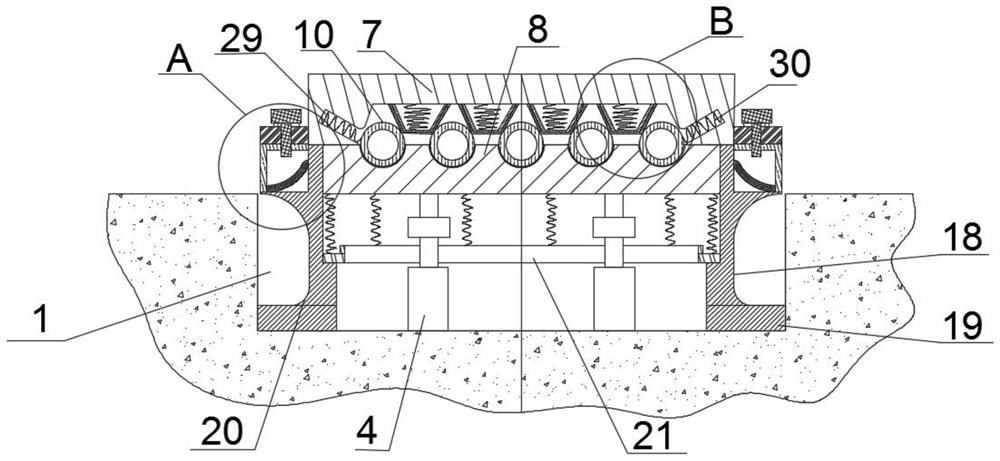
[0052] Such as Figure 1 to Figure 5 As shown, it is an embodiment of the present invention, an electrical embedded pipe protection device, including a support and a positioning pipe frame, the support is located on the lower side of the positioning pipe frame, and the support is suitable for being installed in the embedded groove 1, The embedded part 2 is installed in the embedded groove 1, and the upper end of the embedded part 2 is provided with an external thread;

[0053] The support includes a support frame 3 and a locking sleeve 4. The support frame 3 is connected with the positioning pipe frame. Part 2 threaded connection;

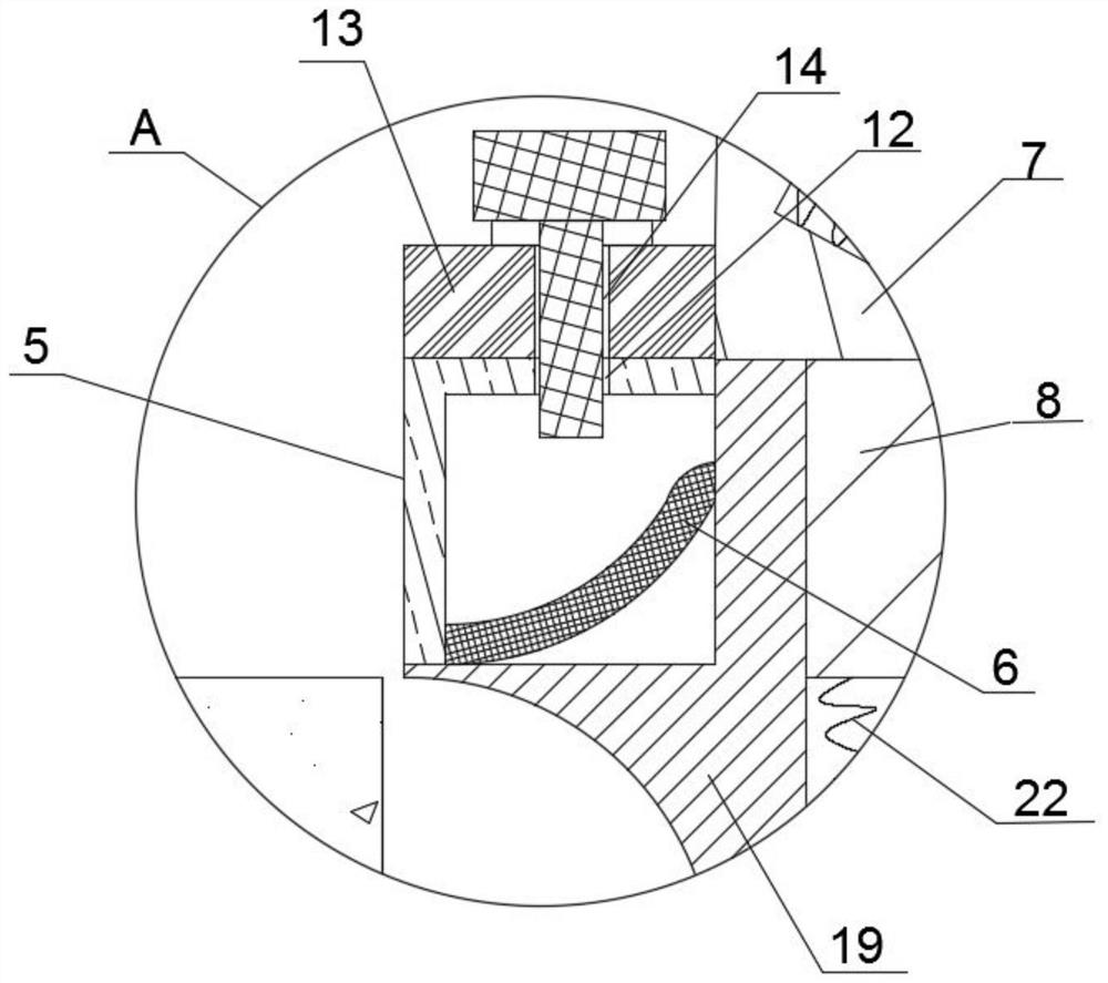
[0054] The support frame 3 includes an anti-seepage part, the anti-seepage part is located at the upper end of the support frame 3, the anti-seepage part is integrally connected with the support frame 3, the anti-seepage part includes a bent outer plate 5 and an arc inner plate 6, and the bent outer plate 5 and the The arc inner plate 6 is fixedl...

Embodiment 2

[0061] Such as Figure 6 and Figure 7 As shown, it is another embodiment of the present invention. On the basis of Example 1, an addition is made: the horizontal part 18 is provided with a mounting hole 23, the mounting hole 23 is vertically arranged on the horizontal part 18, and the mounting hole 23 is installed There are fixed feet 24, the fixed feet 24 are inverted "T" shapes along the working horizontal section, the fixed feet 24 are provided with a first positioning hole 25, and the side of the horizontal part 18 away from the annular plate 21 is provided with a second positioning hole 26, The first positioning hole 25 corresponds to the second positioning hole 26 , and the horizontal portion 18 and the fixing foot 24 are adapted to be threadedly connected by bolts.

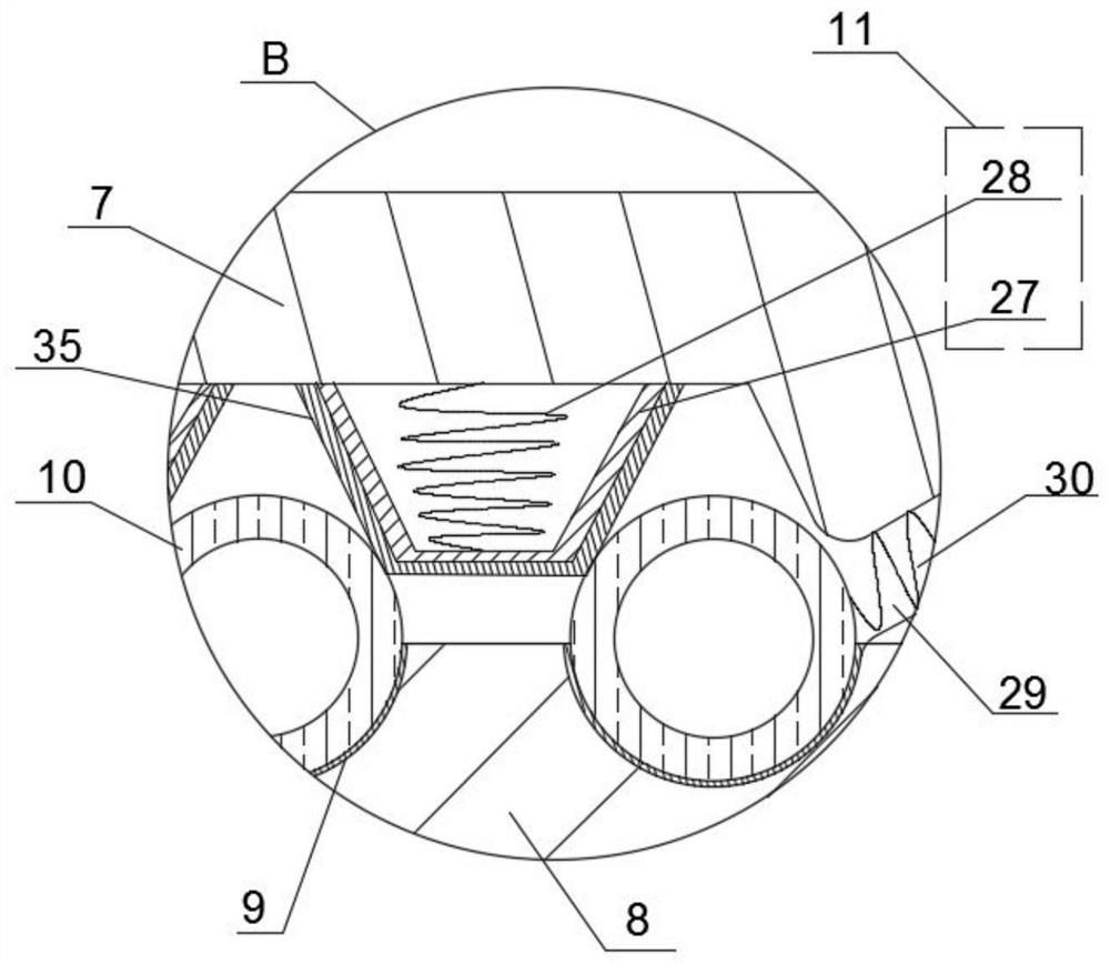
[0062] There are multiple sets of first arc grooves 9, and multiple sets of first arc grooves 9 are arranged horizontally side by side;

[0063] The buffer member 11 includes an extruding plate 27 and a ...

Embodiment 3

[0066] Such as Figure 8 and Figure 9 As shown, it is another embodiment of the present invention. On the basis of Example 2, an addition is made: the lower housing 8 is provided with a connecting column 31, and the connecting column 31 is located between the first arc grooves 9. The connecting column 31 A combination plate 32 is installed on the top, and a groove 33 is arranged under the combination plate 32. The groove 33 is engaged with the connecting column 31. The combination plate 32 is provided with a second arc groove 34, which is suitable for fitting Electrical embedded pipe 10;

[0067] A rubber layer 35 is arranged in the first arc groove 9 and the second arc groove 34 , the rubber layer 35 is arranged under the fixed foot 24 , and the rubber layer 35 is arranged on the surface of the extruding plate 27 .

[0068] A construction method for an electrical embedded pipe protection device, characterized in that it comprises the following steps:

[0069] Step 1. Conc...


PUM


Abstract

The invention discloses an electrical embedded pipe protection device and a construction method thereof, and belongs to the field of building electrical construction. The electrical embedded pipe protection device comprises a supporting piece and a positioning pipe frame, the supporting piece is located in the lower side of the positioning pipe frame, the supporting piece comprises a supporting frame and a locking sleeve, the supporting frame is connected with the positioning pipe frame, the supporting frame is attached to an embedded groove, and the supporting frame comprises an anti-seepage part; the anti-seepage part is located at the upper end of the supporting frame and comprises a bent outer plate and an arc inner plate, and the bent outer plate is fixedly connected with the arc inner plate; the positioning pipe frame comprises an upper shell and a lower shell, a first arc groove is formed in the lower shell, an electrical embedded pipe is suitable for being installed in the first arc groove, a buffer piece is installed on the upper shell, the buffer piece is suitable for being attached to the electrical embedded pipe, and the upper shell is fixedly connected with the supporting frame; the technical problems that in the prior art, an electrical embedded pipe is poor in fixing effect, low in protectiveness, poor in practicability, poor in damping performance and the like are solved.

Description

technical field [0001] The invention belongs to the field of building electrical construction, and in particular relates to an electrical embedded pipe protection device and a construction method thereof. Background technique [0002] In the field of building electrical construction, the protection of electrical embedded pipes plays an important role in subsequent construction. At present, concrete or mortar is mostly used to protect electrical embedded pipes during electrical construction operations. However, the current installation of electrical piping has the following deficiencies: [0003] 1. At present, when installing electrical pre-embedded pipes, it is necessary to lay pipes in the cast-in-place concrete components, or bind the pipes to the steel bars with iron wires, or nail them to the formwork, but they cannot fix the electrical pipes well. If the wall is not built in time, the electrical embedded pipe may be damaged. [0004] 2. At present, the electrical pre-...

Claims


Application Information

Patent Timeline
Patent Type & Authority Applications(China)
IPC IPC(8): H02G3/04H02G3/38H02G1/00E04G21/00
CPCH02G3/0406H02G3/0481H02G3/38H02G3/386H02G1/00E04G21/00
Inventor 李占林王志吕正东胡德帅潘邦全
Owner CHINA MCC17 GRP
Why Eureka
Try Eureka