
A multi-mode combined short-circuit protection circuit and its working method and application

A short-circuit protection and multi-mode technology, which is applied in the direction of emergency protection circuit devices, output power conversion devices, electrical components, etc., can solve the problems of high short-circuit power consumption of high-power switching power supplies, avoid the risk of over-voltage stress, and solve Weak load capacity, solve the effect of large power consumption

Active Publication Date: 2022-03-22
XIAN MICROELECTRONICS TECH INST
View PDF0 Cites 0 Cited by
  • Summary
  • Abstract
  • Description
  • Claims
  • Application Information

AI Technical Summary

Problems solved by technology

[0009] The purpose of the present invention is to provide a multi-mode combined short-circuit protection circuit and its working method and application, which solves the problem of large short-circuit power consumption of high-power switching power supplies, and has the advantage of strong capacitive load capacity

Method used


Image

  • A multi-mode combined short-circuit protection circuit and its working method and application
  • A multi-mode combined short-circuit protection circuit and its working method and application
  • A multi-mode combined short-circuit protection circuit and its working method and application

Examples


Embodiment Construction

[0044] The present invention will be further described in detail below in conjunction with specific embodiments, which are explanations of the present invention rather than limitations.

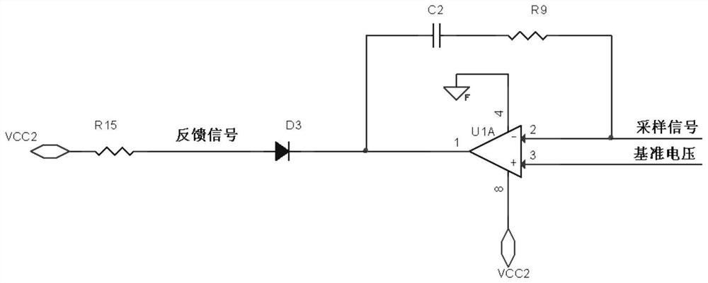
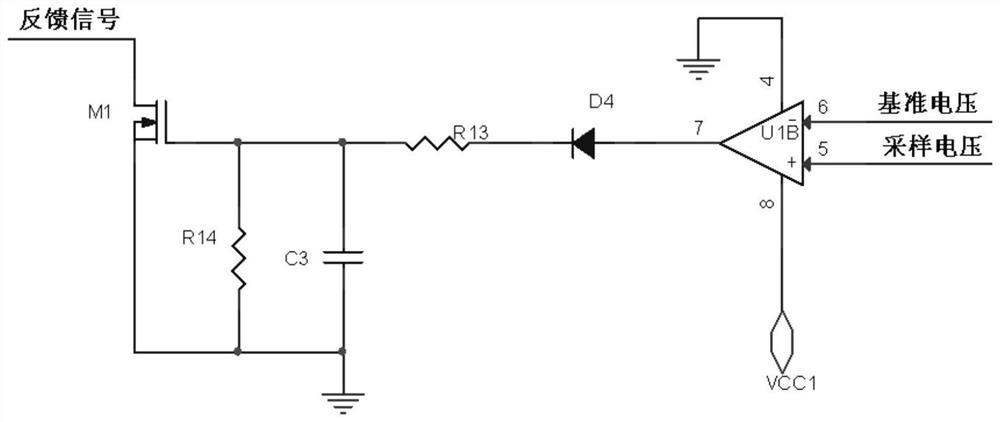
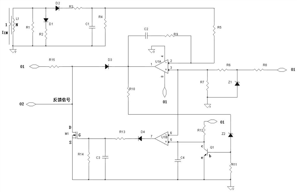
[0045] Such as image 3 As shown, the present invention discloses a multi-mode combined short-circuit protection circuit, including a sampling circuit, a constant current protection circuit, a hiccup protection circuit, a reference reference voltage circuit and a voltage divider circuit; the sampling circuit includes a current transformer L1, a resistor R1, Resistor R2, resistor R3, resistor R4, resistor R5, diode D1, diode D2 and capacitor C1; the reference voltage circuit includes resistor R6, resistor R7, resistor R8 and voltage regulator tube Z1; the voltage divider circuit includes resistor R10, resistor R11, Resistor R12, voltage regulator tube Z2, capacitor C4 and transistor Q1; constant current protection circuit includes operational amplifier U1A, resistor R15, diode D3, capacitor C2...


PUM


Abstract

The invention belongs to the technical field of short-circuit protection circuits, and discloses a multi-mode combination short-circuit protection circuit and a working method thereof, which specifically include a sampling circuit, a constant current protection circuit, a hiccup protection circuit, a reference reference voltage circuit and a voltage dividing circuit; a constant current circuit The protection circuit includes the operational amplifier U1A, and the hiccup protection circuit includes the operational amplifier U1B. When the output of the switching power supply is short-circuited, the constant current protection is performed first, and then the hiccup protection is performed, and the hiccup protection mode can be turned on when the set constant current protection time is reached. If the fault persists, the protection circuit repeats the working mode of "constant current protection-hiccup protection"; the short-circuit fault of the switching power supply is eliminated and the normal function is restored. The short-circuit protection circuit not only has the characteristics of strong capacitive load capacity of constant current protection, but also has the characteristics of low short-circuit power consumption of hiccup protection. The problem of high short-circuit power consumption of the power supply also has the advantage of strong capacitive load capacity.

Description

technical field [0001] The invention belongs to the technical field of short-circuit protection circuits, and in particular relates to a multi-mode combination short-circuit protection circuit and its working method and application. Background technique [0002] Switching power supplies continue to develop in the direction of high power, small size, high efficiency, and high reliability. With the advancement of high-efficiency technology, the power dissipation of switching power supplies has been effectively controlled, the volume size has been continuously reduced, and the power density has become higher and higher. However, the difficulty of short-circuit protection circuit design has continued to increase, which restricts the improvement of the reliability of switching power supplies. There are two commonly used short-circuit protection circuits at present, one is a constant current protection circuit, and the other is a hiccup protection circuit. [0003] (1) Constant c...

Claims


Application Information

Patent Timeline
Patent Type & Authority Patents(China)
IPC IPC(8): H02M1/32H02H7/12
CPCH02M1/32H02H7/1203H02H7/1213
Inventor 王鲁曹鹏辉张小峰罗伟付翀丽王俊峰
Owner XIAN MICROELECTRONICS TECH INST
Learn More