Manufacturing method of vacuum cup with composite inner container

A manufacturing method and technology of thermos cups, which are applied in the field of thermos cups, can solve the problems of heavy overall quality, difficulty in forming, and wall thickness of the inner tank, etc.

Active Publication Date: 2021-06-22
ZHEJIANG FEIJIAN IND & TRADE
View PDF10 Cites 5 Cited by
  • Summary
  • Abstract
  • Description
  • Claims
  • Application Information

AI Technical Summary

Problems solved by technology

[0003] The invention provides a new manufacturing method for a thermos cup with a composite liner, aiming at the defects in the prior art that the inner wall of the composite thermos cup is thicker, the overall quality is heavier, and the three-layer composite board is difficult to form when manufacturing the inner pot. method

Method used


Image

  • Manufacturing method of vacuum cup with composite inner container
  • Manufacturing method of vacuum cup with composite inner container
  • Manufacturing method of vacuum cup with composite inner container

Examples


Embodiment 1

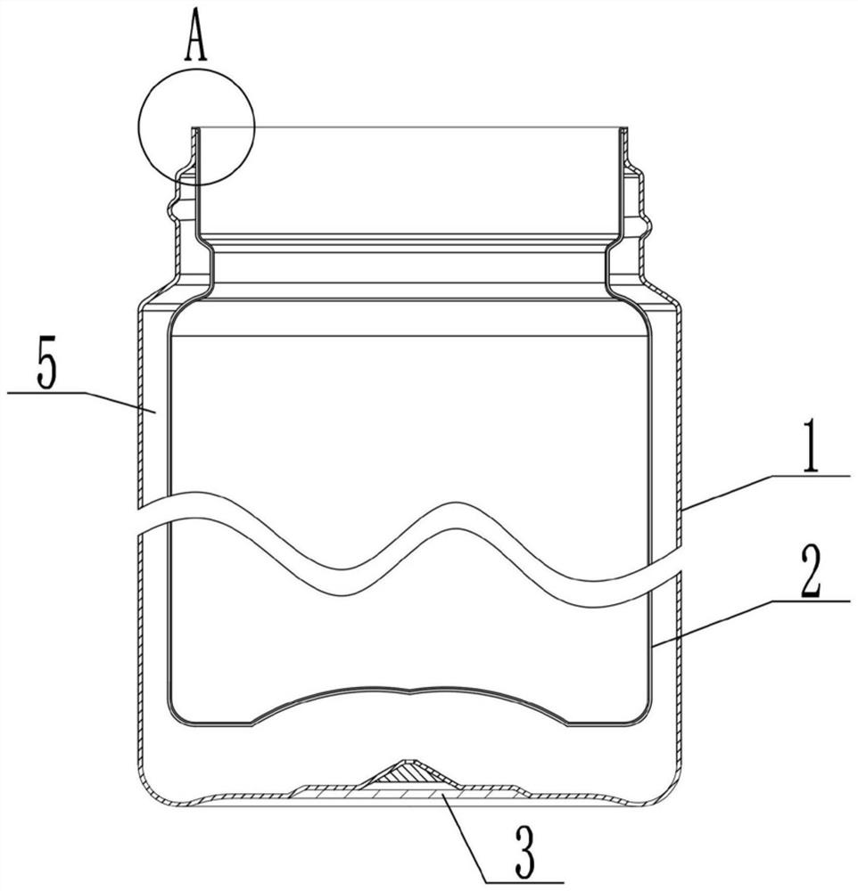
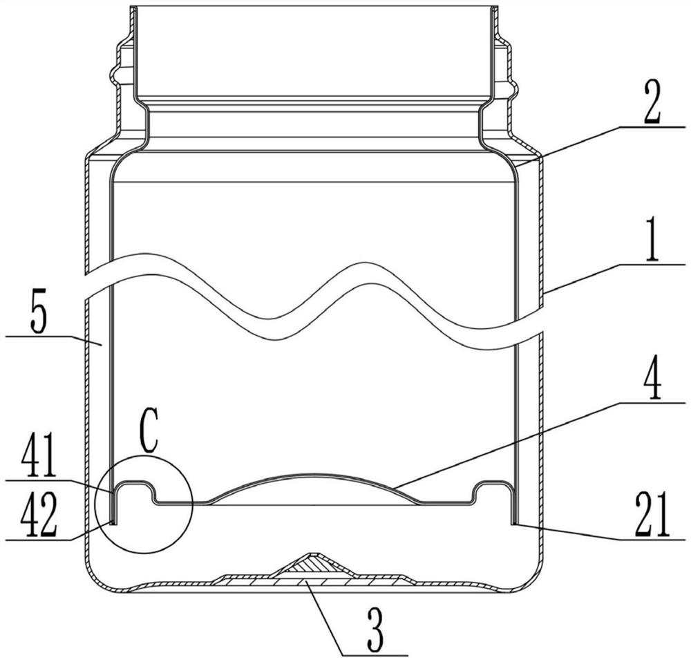
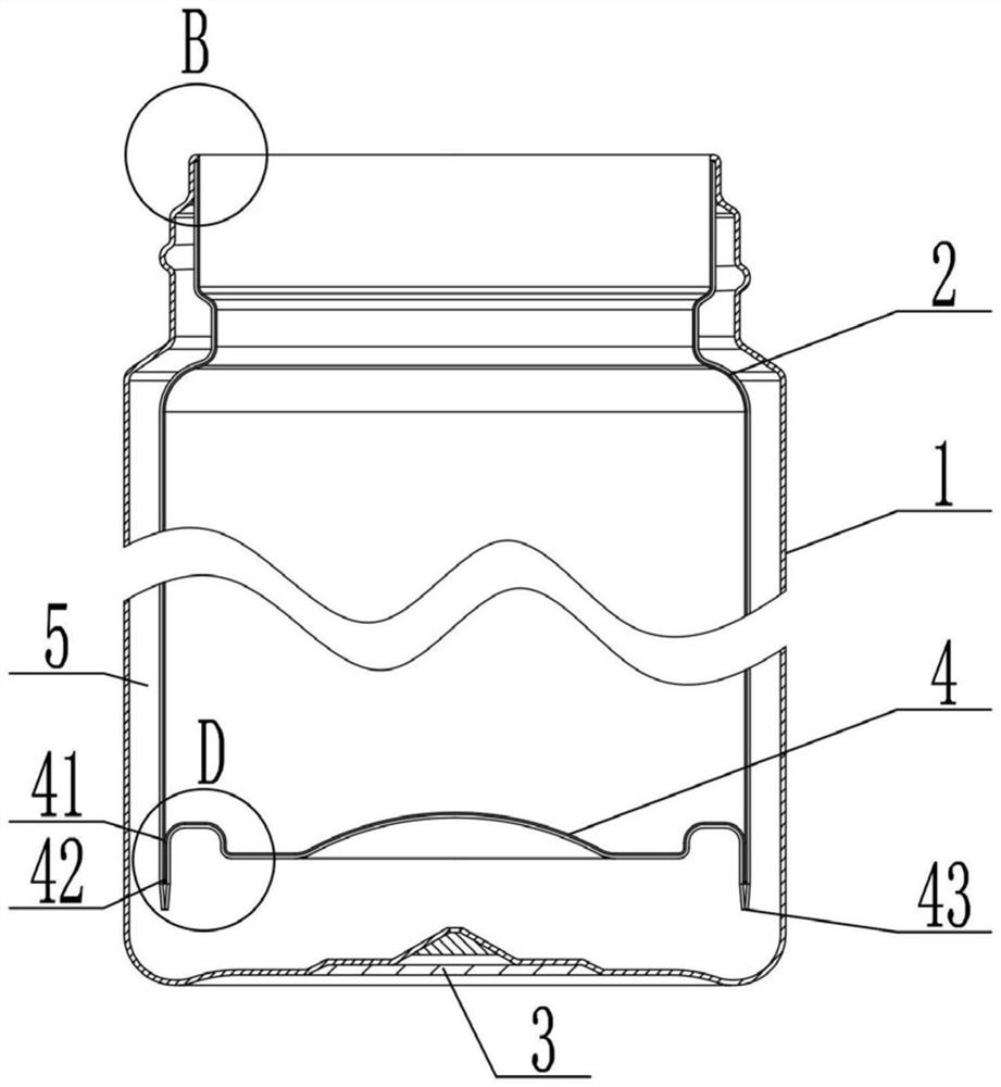
[0056] A method for manufacturing a thermos cup with a composite liner, comprising a stainless steel shell 1, a cup bottom 3, the cup bottom 3 being welded to the bottom of the stainless steel shell 1, and a composite liner 2, the composite liner 2 It is made of a two-layer composite plate with a titanium inner layer 22 and a steel outer layer 23. The mouth of the stainless steel shell 1 is welded to the mouth of the composite inner tank 2, and the stainless steel shell 1 and the composite inner tank are welded together. A vacuum layer 5 is formed between the bladders 2, and its preparation process includes the following steps:

[0057] Q1: Take a two-layer composite plate with a titanium inner layer 22 and a steel outer layer 23, and cut it into discs;

[0058] Q2: Clean the above-mentioned wafers, dry them and place them in a vacuum furnace for annealing, raise the temperature of the vacuum furnace to 600°C within 15 minutes, keep the temperature for 30 minutes, and then use...

Embodiment 2

[0077] As a preference, in the step Q7, the mouth of the steel outer layer 23 is shortened first, the end face of the titanium inner layer 22 is higher than the end face of the steel outer layer 23 and forms a 0.5mm step, and then the The stainless steel shell 1 is matched with the mouth, the end face of the mouth of the stainless steel shell 1 is flush with the mouth end face of the steel outer layer 23, and then the mouth of the stainless steel shell 1 is connected with the mouth of the steel outer layer 23. Laser welding, and then the raised steps are bent outwards of the composite liner 2 and welded to the mouth of the stainless steel shell 1 .

[0078] Other implementation modes in this embodiment are the same as those in Embodiment 1.

Embodiment 3

[0080] Preferably, the groove 21 has a width of 0.4 mm, and is filled with powdered glass or metal solder for brazing.

[0081] Other implementation modes in this embodiment are the same as those in Embodiments 1-2.


PUM

PropertyMeasurementUnit
widthaaaaaaaaaa
thicknessaaaaaaaaaa
thicknessaaaaaaaaaa

Abstract

The invention discloses a manufacturing method of a vacuum cup with a composite inner container. The vacuum cup comprises a stainless steel outer shell, a cup bottom and the composite inner container, the composite inner container is made of a two-layer composite board with a titanium inner layer and a steel outer layer, and the manufacturing method of the vacuum cup comprises the following steps that Q1, the composite board is taken to be cut into wafers; Q2, the wafers are cleaned and annealed; Q3, the wafers are subjected to fine flattening; Q4, the wafers are stretched, and a composite inner container blank is prepared; Q5, the composite inner container blank is formed into the composite inner container; Q6, the composite inner container is subjected to opening flattening and spinning; Q7, the stainless steel outer shell and the composite inner container are welded twice; Q8, opening grinding treatment is conducted, and a cup body is manufactured; and Q9, the cup body is vacuumized, the cup bottom is welded to the bottom of the stainless steel outer shell, and electrolysis and surface treatment are conducted. According to the manufacturing method of the vacuum cup with the composite inner container, the two-layer composite board with the titanium inner layer and the steel outer layer is adopted, the defect that an existing manufacturing process is complex is overcome, the thickness and the weight of the composite inner container are reduced, and the air tightness of the vacuum layer is enhanced.

Description

technical field [0001] The invention relates to a thermos cup, in particular to a method for manufacturing a thermos cup with a composite liner. Background technique [0002] Some existing composite thermos cups on the market have defects such as thicker inner wall, heavier overall quality, and poor airtightness of the vacuum layer. For example, in the CN202011059269.9 patent, three-layer composite plates of stainless steel, aluminum, and titanium are mainly used for inner tank manufacturing. , but the tensile coefficients of the three materials are different, and it is difficult to form; other patents also use stainless steel, aluminum, and titanium composite plates as the middle layer, the titanium inner tank is welded to the titanium of the middle layer, and the stainless steel to the middle layer is welded to stainless steel. There are technical problems such as poor airtight performance and short duration of vacuum performance. Contents of the invention [0003] The ...

Claims


Application Information

Patent Timeline
Patent Type & Authority Applications(China)
IPC IPC(8): B23P15/00A47G19/22
CPCB23P15/00A47G19/2288A47G19/2205
Inventor 施兴富吴林军王志杰赵洪蓝海
Owner ZHEJIANG FEIJIAN IND & TRADE
Why Eureka
Try Eureka